



March 15, 2016
Today’s data centers are the home to diverse bandwidth-demanding devices, like servers, storage systems, and backup devices which are interconnected by networking equipment. All these devices drive the need for reliable and manageable cabling infrastructure with higher performance and more flexibility for today and future growth. While managing the cabling in data centers, two main processes are included: planning the cabling infrastructure and implementing the cables.
As networking equipment becomes denser, and port counts in data centers increase to several hundred ports, managing cables connected to these devices becomes a difficult challenge. Thus, during planning the cabling infrastructure, it’s wise to do the following:
Choosing Fiber Cable AssemblyThis assembly has a single connector at one end of the cable and multiple duplex breakout cables at the other end, an alternative to avoid cable management. The LC (Lucent Connector) -MPO (Multifiber Push-On) breakout cable assemblies are designed to do just that. The idea is to pre-connect the high-density, high- port-count LC equipment with LC-MPO breakout cable to dedicated MPO modules within a dedicated patch panel, reducing equipment cabling clutter and improving cable management. This image below show the LC-MPO breakout cable assembly that consolidates six duplex LC ports into one MPO connection.

Nowadays, this breakout technology is widely used in 40 Gigabit Ethernet (GbE) applications. Like QSFP-4X10G-AOC10M, this product is the QSFP to four SFP+ active optical breakout cable assembly with the 10m short reach.
Using Color to Identify CablesColor coding simplifies management and can save you hours when you need to trace cables. Cables are available in many colors (table shown below). For instance, multi-mode fiber (MMF) looks in orange (OM1, OM2) and in aqua (OM3), while yellow is usually the color of single-mode fiber (SMF) which is taken as the transmission media when the required distance is as long as 2km, or 10km . Take WSP-Q40GLR4L for example, this 40GBASE-LR4L QSFP+ transceiver works through SMF for 2km link length.

While implementing the cables, the following tasks should be obeyed by.
Testing the LinksTesting cables throughout the installation stage is imperative. Any cables that are relocated or terminated after testing should be retested. Although testing is usually carried out by an authorized cabling implementer, you should obtain a test report for each cable installed as part of the implementation task.
Building a Common Framework for the Racksthis step is to stage a layout that can be mirrored across all racks in data centers for consistency, management, and convenience. Starting with an empty 4-post rack or two, build out and establish an internal standard for placing patch panels, horizontal cable managers, vertical cable managers, and any other devices that are planned for placement into racks or a group of racks. The INTENTION is to fully cable up the common components while monitoring the cooling, power, equipment access, and growth for the main components in the racks.
A good layout discourages cabling in between racks due to lack of available data ports or power supply ports, allowing more power outlets and network ports than you need. This will save you money in the long run as rack density increases, calling for more power and network connectivity. Using correct length cables, route patch cables up or down through horizontal patch panels alleviates overlapping other ports. Some cable slack may be needed to enable easy removal of racked equipment.
DocumentationTypically, the most critical task in cable management is to document the complete infrastructure: including diagrams, cable types, patching information, and cable counts. It’s advised update the documentation and keep it accessible to data center staff on a share drive or intranet Web site.
Stocking Spare CablesIt’s suggestible to maintain an approximately the same amount on the installed cabling and ports in use, so as to face the environment variation or emergency.
Understanding the above-mentioned information about cabling planning and implementation helps you to have a scalable, dependable and manageable cabling infrastructure in data centers. Fiberstore offers many cable management tools, including fiber termination box, cable ties, and distribution cabinet. For more information about cable management solutions, you can visit Fiberstore.
Originally published at www.fiber-optic-components.com/cabling-data-center-process-planning-implementing-its-infrastructure.html
Posted by: fernxu123 at
03:32 AM
| No Comments
| Add Comment
Post contains 704 words, total size 6 kb.
March 10, 2016
The increasing availability of virtualization applications and unified networking infrastructure puts extreme input/output (I/O) demands on 1 Gigabit Ethernet (GbE), making data centers facing bandwidth challenges. Deploying 10GbE infrastructure can address these problems by delivering greater bandwidth, simplifying network, and lowering power consumption.
Well, the deployment of 10GbE requires cost-effective solution. In general, there are several 10GbE interfaces to choose from, including CX4, SFP+ fiber, SFP+ Direct Attach Copper (DAC), and 10GBASE-T. As for CX4, it’s an older technology that does not meet high density requirements. Although most deployment chooses SFP+ fiber (eg. F5-UPG-SFP+-R) solution, fiber is in no case cost-effective. Besides, SFP+ DAC is limited by its short reach. In such a case, 10GBASE-T is selected as the less power-consuming and cost-saving solution for 10GbE. This article details at what are the reasons that drive the 10GBASE-T to become the suitable 10GbE media option.
Firstly, let’s figure out what is 10GBASE-T. 10GBASE-T, or IEEE 802.3an-2006, is a standard released in 2006 to provide 10Gbit/s connections over unshielded or shielded twisted pair cables, with distances up to 100 meters (330 ft) with RJ45 connectors. 10GBASE-T cable infrastructure can also be used for 1000BASE-T, allowing a gradual upgrade from 1000BASE-T using auto-negotiation to select which speed to use.
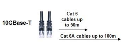
Listed below are several reasons why 10GBASE-T become the 10GbE media option.
Like other copper network implementations using BASE-T standards, 10GBASE-T works for link lengths up to 100 meters, giving network designers a far greater level of flexibility in connecting devices in the data center. Able to realize flexible reach, 10GBASE-T can accommodate either top of the rack, middle of row, or end of the row network topologies, making server placement even more easy and convenient.
10GBASE-T is backward-compatible with existing 1GbE networks, meaning that it can be deployed based on existing 1GbE switch infrastructures in data centers that are cabled with CAT6 and CAT6A (or above) cabling. In other words, when migrating from 1GbE to 10GbE, 10GBASE-T provides an easy path, saving cost.
In widespread deployment of 10GbE networks using 10GBASE-T interface, one challenge lies in the fact that the early physical layer interface chips (PHYs) consumed too much power. The original gigabit chips were roughly 6.5 Watts per port. With technology improvements, the chips improved from one generation to the next, leading to less 1 W per port for 1GbE interfaces. It’s the same with 10GBASET. And owing to the manufacturing processes, the 10GBASE-T reduction in power consumption has been made possible. The figure below shows the relationship between power consumption and wavelength.
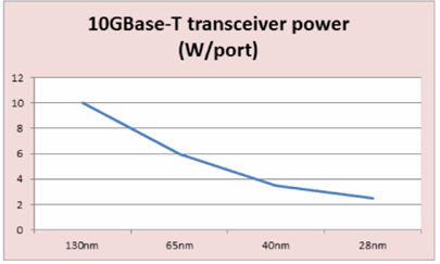
When 10GBASE-T adapters were first introduced in 2008, they required 25 W of power for a single port, and later, power has been reduced thanks to the successive generations of developing newer and smaller process technologies. The latest 10GBASE-T adapters require less than 6 W per port,which makes 10GBASE-T suitable for motherboard integration and high-density switches.
Depending on packet size, latency for 10GBASE-T ranges from just over 2 µs to less than 4 µs—a much tighter latency range. For Ethernet packet sizes of 512 bytes or larger, 10GBASE-T’s overall throughput offers an advantage over 1000BASE-T. Latency for 10GBASE-T is more than three times lower than 1000BASE-T with larger packet sizes. For those enterprise applications that have been operating for years with 1000BASE-T latency, 10GBASE-T latency only makes things better. Many products designed for Local Area Network (LAN) purposely add small amounts of latency to reduce power consumption or CPU overhead.
Broad use of 10GBASE-T interface simplifies data center infrastructures, making it easier to manage server connectivity while delivering the bandwidth needed for heavily virtualized servers and I/O-intensive applications. As the cost continues to fall, and new technological processes further lower power consumption, all these make 10GBASE-T suitable for integration on server motherboards.
10GBASE-T offers the flexible reach, and its backward compatibility with existing 1GbE networks makes it the ideal cost-effective media option for 10GbE infrastructure. As a professional fiber optic product manufacturer and supplier, Fiberstore provides countless 10GBASE-T transceivers for 10GbE applications. Of course, besides 10GBASE-T, other 10GBASE standard transceivers also available in Fiberstore, such as 10GBASE-ER SFP+ (J9153A). For more information about 10GbE interfaces, you can visit Fiberstore.
Originally published at www.fiber-optic-components.com/why-choose-10gbase-t-interface-for-10gbe-infrastructure.html
Posted by: fernxu123 at
03:49 AM
| No Comments
| Add Comment
Post contains 713 words, total size 6 kb.
March 08, 2016
Over the years, Ethernet technologies have evolved rapidly and amazingly to meet the never-ceasing requirements of higher bandwidth and faster data transmission speeds for high quality network applications, such as live video and video download with high resolution. Through this great evolution, Ethernet technology standards have been designed, like 10 Gigabit Ethernet (GbE).
After IEEE Standard 802.3ae- 2002 for 10GbE was ratified several years ago, some enterprises have begun to deploy 10GbE in their data centers to support bandwidth-needing applications. Before deploying 10GbE, as matter of fact, there are many things that should attract your attention. Here this article lists two important things you need to consider for a reliable 10GbE deployment: 10GbE cabling choices, and 10GbE transceiver types.
Along with the technological revolution, cables used for transmission also experienced progressive development. There are two physical media available for 10GbE transmission: fiber and copper.
10GbE Fiber Cabling ChoicesFiber cables fall on two classifications: single-mode fiber (SMF) and multi-mode fiber (MMF). In SMF, there is only one path for light, while in MMF light flow through multiple paths. SMF is intended for long distance communication and MMF is used for distances of less than 300 m. Commonly used 10GbE ports designed for SMF are 10GBASE-LR, 10GBASE-ER and 10GBASE-ZR, and the ports specified for MMF are 10GBASE-SR and 10GBASE-LRM. It’s of great importance to choose these ports 10GbE transmission when link lengths matter. For example, you can choose a J9150A transceiver when the required distance is less than 300m. In a word, the form factor options depend on your link lengths.
10GbE Copper Cabling ChoicesAs the structured cabling techniques become mature, copper cabling technology also grasps the chance to develop itself. And more and more people start to choose copper cables as the medium for 10GbE transmission. 10GBASE-T and SFP+ direct attach cables (DAC) standards symbolize copper applications.
10GBASE-T, or IEEE 802.3an-2006, is a standard released in 2006 to provide 10Gbit/s connections over unshielded or shielded twisted pair cables, over distances up to 100 metres (330 ft). It requires the Cat 7 or Cat 6A to reach 100 meters, but can still work on Cat 6, Cat 5E, or even Cat 5 cable when reduced distances are required.
SFP+ DAC is the latest standard for optical transceivers, and it connects directly into an SFP+ housing. In SFP+ DAC cabling assembly, no optical transceiver is used at each end. A cable was invented with each end physically resembling a SFP+ transceiver, but with none of the expensive electronic components. This creation is known as DAC. Actually, besides 10GbE applications, DAC is also considered as a cost-effective solution to replace fiber patch cables sometimes in 40GbE systems. Like QSFP-H40G-ACU10M, this Cisco 40G cabling product is the QSFP to QSFP direct attach passive copper cable assembly designed for 40G links.

After choosing cables, you need to select devices that connect these cables to your networks. These devices are transceivers. 10GbE has four transceiver types: XENPAK (and related X2 and XPAK), GBIC, SFP and SFP+.
XENPAK is a Multisource Agreement (MSA) that defines a fiber-optic or wired transceiver module which conforms to the 10 Gigabit Ethernet (10GbE) standard of the Institute of Electrical and Electronics Engineers (IEEE) 802.3 working group.
GBIC stands for Gigabit Interface Converter. It is a common type of optical transceiver module which converts serial electric signals into serial optical signals and vice versa. The GBIC is typically employed in fiber optic and Ethernet systems as an interface for high-speed networking. Common applications include Fibre Channel and Gigabit Ethernet.
SFP (small form-factor pluggable) can be regarded as the upgrade version of GBIC module. Unlike GBIC with SC fiber optic interface, SFP is with LC interface and the main body size of SFP is only about half of GBIC so that it can save more space. There are several types of SFP modules, SX, LX, EX, etc. Among them, 1000BASE-SX SFP is the most widely used. This type works with multi-mode fiber (MMF) for linking. When used with 62.5 micron MMF, its max-working span is around 220 meters, while when used with 50 micron MMF, its max-working span is around 550 meters. Fiberstore compatible Cisco SFP-GE-S product is designed to realize 550 -meter reach through 50 micron MMF.

SFP+, also called SFP Plus, is short for enhanced small form-factor pluggable, an enhanced version of the SFP that supports data rates up to 16Gbit/s.
After discussion, maybe you have obtained a better understanding of 10GbE cables and transceivers, which helps you to better choose the right devices for your 10GbE applications. Fiberstore supplies various numbers of 10GbE cables and transceivers which are quality assured. For more information about 10GbE solutions, you can visit Fiberstore directly.
Originally published at www.fiber-optic-components.com/consider-two-things-before-deploying-10-gigabit-ethernet.html
Posted by: fernxu123 at
02:54 AM
| No Comments
| Add Comment
Post contains 801 words, total size 7 kb.
March 03, 2016
Since Ethernet technology is born in 1970s, it has evolved continuously to meet the never-ceasing demands of even faster rates of data transmission, such as 10 Gigabit Ethernet (GbE). Along with this ongoing evolution, the cabling technologies that support the 10GbE applications have also advanced, so as to provide greater bandwidth to transmit data with reasonable cost and decreased complexity. Maybe you have few insights in this evolution. Don’t worry. This text mainly talks about the evolution of 10GbE cabling technologies, including fiber and copper cabling technologies.
The Institute of Electrical and Electronics Engineers (IEEE) 802.3 working group has published several standards regarding 10GbE, including 802.3ae-2002 (fiber -SR, -LR, -ER), 802.3ak-2004 (CX4 copper twin-ax InfiniBand type cable), etc. Actually, the evolution of cabling technologies have walked in step with that of 10GbE standards, especially associated with the difference between IEEE802.3ae and IEEE802.3ak standards.
Ratified in June 2002, the IEEE802.3ae standard outlined the following port types.
10GBASE-SR—It supports 10GbE transmission over standard multi-mode fiber (MMF) with distances of 33m on OM1 and 86m on OM2. Using 2000 MHz/km MMF (OM3), up to 300-m link lengths are possible. Using 4700 MHz/km MMF (OM4), up to 400 meter link lengths are possible. Like SFP-10G-SR-S (shown below), this Cisco 10GBASE-SR module listed in Fiberstore is able to support up to 300m using OM3 at the maximum data rate of 10.3125Gbps. In addition, SR is the lowest-cost optics (850nm) of all defined 10GbE optics.

10GBASE-LR—This port type uses higher cost optics (1310nm) than SR and requires more complex alignment of the optics to support 10km link length over single-mode fiber (SMF).
10GBASE-ER—It’s a port type for SMF and uses the most expensive optics (1550nm) lasers, enabling a reach of 40km over engineered links and 30km over standard links.
Approved in February 2004, this IEEE802.3ak standard only defined 10GBASE-CX4—the first 10GbE copper cabling standard.
10GBASE-CX4—It’s a low-cost 10GbE solution intended for copper cabling with short-distance connectivity. Its affordability and wide availability makes 10GBASE-CX4 ideal for wiring closet and data center connectivity.
The CX4 standard transmits 10GbE over four channels using twin-axial cables which originated from Infiniband connectors and cable. The CX4 standard committee defined that the cables should be tighter in electrical specifications. Therefore, CX4 standard is not appropriate when longer length (>10 Infiniband cable is required. And It’s recommended to use only cables that are designed to meet IEEE 802.3ak specifications.
Another aspect of the CX4 cable is the rigidity and thickness of the cable. The longer the length used, the thicker the cable is. CX4 cables must also be factory-terminated to meet defined specifications.
After comparison between IEEE802.3ae and IEEE802.3ak standards, here goes a picture about the cabling cost and distance considerations.
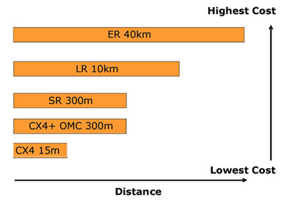
Besides IEEE802.3ae and IEEE802.3ak standards, there also exists IEEE802.3an standard. Proposed in November 2002, IEEE802.3an defined 10GBASE-T using unshielded twisted-pair (UTP) style cabling. The goal of this copper standard is to improve the performance and distance of copper cabling at a cost that is lower or similar to fiber.
From the above introduction, the evolution of cabling technologies is associated with the evolution of 10GbE standards. As 10GbE deployment becomes a commonplace, it’s of great importance to make wise cabling strategies.
Spurred by the demand for faster application speeds, cabling technologies evolved to support the 10GbE standards, thus to better accommodate bandwidth-intensive applications and traffic types. With 10GbE technology being pervasive, it’s necessary to understand the the different 10GbE standards and cabling technologies (mentioned above). Fiberstore supplies 10GbE application solutions, transceivers, copper and fiber cables all included, like AFBR-703SDZ-IN2, a 10GBASE-SR SFP+ transceiver. For more information about 10GbE system solutions, you can visit Fiberstore.
Originally published at www.fiber-optic-components.com/the-evolution-of-10gbe-cabling-technologies.html
Posted by: fernxu123 at
03:27 AM
| No Comments
| Add Comment
Post contains 615 words, total size 6 kb.
March 01, 2016
Contaminated fiber optic cables can often lead to degraded network performance or even failure of the whole system. As such, to ensure that fiber optic cables can yield the best possible results of network performance, and it’s of great significance for network engineers to keep in mind how to handle fiber optic cables. Do you have any ideas? This text gives the guide to fiber optic cable handling rues.
Before delving into how to handle fiber optic cables, introduction to their makeup elements is required.
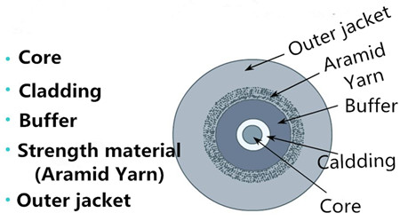
Fiber optic cable generally consists of fiver elements (figure shown above): the optic core, optic cladding, a buffer material, a strength material and the outer jacket. Commonly made from doped silica (glass), the optic core is the light-carrying element at the center of the cable. Surrounding the core is the optic cladding, whose combination with the core makes the principle of total internal reflection possible. Surrounding the cladding is a buffer material used to help shield the core and cladding from damage. A strength material surrounds the buffer, preventing stretch problems when the fiber cable is being pulled. The outer jacket is added to protect against abrasion, solvents, and other contaminants.
The outer jacket on fiber optic patch cord is often color-coded to indicate the fiber types being used. For instance, multi-mode fiber (MMF) is usually in orange to distinguish from the color yellow for single-mode fiber (SMF) through which fiber optic transceivers realize relatively long distance, such as MGBLX1. This Cisco 1000BASE-LX SFP transceiver is able to achieve 10km link length over SMF.
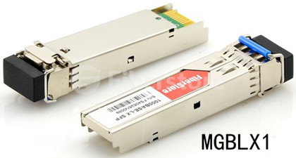
Despite its outer protection mentioned above, fiber optic cable is still prone to damage. In such as case, a series of fiber cable handing rules are made to ensure that a cable is handled properly, so as to maintain the optimized performance, minimum insertion loss and safe working environments.
Rule 1: The exposed fiber end from coming in contact with all surfaces should be protected. If you contact the fiber with hard surfaces, then the end of it shall be scratched or chipped, causing the degraded performance.
Rule 2: It’s highly recommenced to lean the connector (plug) end each time it is inserted into an adapter, since since a dirty connector will contaminate an adapter.
Rule 3: If a fiber needs to be pulled, use the connector strain relief. Directly pulling on the fiber may result in the glass breaking.
Rule 4: It’s ill-advised to use your hands to clean a fiber work area. If you use your hands to wipe clean a work area, a piece of glass may get lodged into your hands. Considering the size of the glass, this glass may not be visible to the naked eye, bringing about eye damage.
Rule 5: If possible, always keep a protective cap on unplugged fiber connectors, because covering the adapters and connectors will help to avoid contamination and collection of residue. Besides, store unused protective caps in a resealable container in order to prevent the possibility of the transfer of dust to the fiber. Locate the containers near the connectors for easy access.

Rule 6: It’s suggestible to use fiber-cleaning materials only once. If optic grade wipes are used to clean the fiber end, they should be discarded immediately after the fiber surface has been wiped to avoid contamination.
Rule 7: The minimum bend radius of the fiber optic cable must be maintained. Surpassing the bend radius may cause the glass to fracture inside the fiber optic cable. Equally, to cause a twist of the cable is also not proposed.
Rule 8: Never look into a fiber while the system lasers are on. Eye damage may occur if you stare directly at a fiber end which is working. Always make sure that the fiber optic cables are disconnected from the laser source, prior to inspection.After discussion, these handling rules may help you to deal with fiber optic cables and improve your network performance.
Proper handling procedures for fiber optic cables are needed to eliminate the possibility of being contaminated or damaged, and provide a clean environment for the network system. Fiberstore supplies many different types of fiber optic cables with high quality for various applications, like MTP cable. You can visit Fiberstore for more information about fiber optic cables.
Originally published at www.fiber-optic-components.com/fiber-optic-cable-handling-rules.html
Posted by: fernxu123 at
03:16 AM
| No Comments
| Add Comment
Post contains 730 words, total size 6 kb.
February 25, 2016
Defined by the Electronic Industries Association and Telecommunications Industry Association (commonly known as EIA/TIA), CAT5 (Category 5) cable is the copper wiring using twisted pair technology, designed for Ethernet networks. The term "Category†refers to the classifications of UTP (unshielded twisted pair) cables. Since its inception in the 1990s, CAT5 has become one of the most popular types of of all twisted pair cable types which include CAT3, CAT4, CAT5, CAT6, etc. This article details CAT5 used in copper networks from its working principles, its standard, as well as its installation considerations.
CAT5 is widely used in 100BASE-TX and 1000BASE-T Ethernet networks. CAT5 typically contains four pairs of copper wire. In 100BASE-TX standard, the signals are transmitted across only two of the CAT5 pairs. One pair is used to transmit signals, and the second pair receives the signals, leaving the other two unused in signal transmission. What’s more, the 100BASE-TX signals only run in one direction across the pairs. As technology advanced, the 1000BASE-T Gigabit Ethernet (GbE) standard was developed. 1000BASE-T standard utilizes all four copper pairs to transmit up to 250 megabits of data per second (Mbps) in full duplex transmission across each pair. That is to say, each pair is able to transmit and receive signals simultaneously. 1000BASE-T modules (eg. GLC-T) functioning over CAT 5 with RJ-45 connector achieve full duplex transmission with link length up to 100m (328ft).

There are two standards for CAT5 wiring, EIA/TIA-568A and EIA/TIA-568B. The following passages mainly discuss EIA/TIA-568A.
The TIA-EIA-568-A standard defined the following three main parameters for testing Category 5 cabling installations: wiremap, attenuation, and Near End Crosstalk (NEXT).
Wiremap is a continuity test. It assures that the conductors that make up the four twisted pairs in the cable are continuous from the termination point of one end of the link to the other. This test assures that the conductors are terminated correctly at each end and that none of the conductor pairs are crossed or short-circuited.
Attenuation is the loss of signal, as it is transmitted from the end of the cable to the opposite end at which it is received. Attenuation, also referred to as Insertion Loss, is measured in decibels (dB). For attenuation, the lower the dB value is, the better the performance is, and of course less signal is lost. This attenuation is typically caused by absorption, reflection, diffusion, scattering, deflection.
Near End Crosstalk (NEXT) measures the amount of signal coupled from one pair to another within the cable caused by radiation emission at the transmitting end.If the crosstalk is great enough, it will interfere with signals received across the circuit. Crosstalk is measured in dB. The higher the dB value, the better the performance, more of the signal is transmitted and less is lost due to coupling.

After testing parameters are mentioned above, here goes the notes of CAT 5 installation.
- Never pull CAT5 copper wire with excessive force. The CAT5 tension limitation is 25 lbs, much lower than standard audio/video cable.
- Never step on, crush, or crimp CAT5.
- Avoid periodic sags; vary the intervals if the cable must sag.
- Do not bend CAT5 wire tightly around a corner; ensure that it bends gradually, so that a whole circle would be at least two inches in diameter.
- Do not allow knots or kinks, even temporarily.
- Never run CAT5 parallel to power wiring closer than six inches.
- Avoid splices. Every splice degrades the line.
Although CAT5 is superseded by CAT5e in many applications, most CAT5 cable meets Cat5e standards and it’s still a commonplace in Local Area Networks (LANs). Many copper networks choose CAT5 as their transmission media because of its low price and high performance. Fiberstore supplies many CAT5 RJ45 pluggable modules, like 100BASE-TX, and 1000BASE-T transceivers (eg. SFP-GE-T). For more information about copper network solutions, you can visit Fiberstore.
Originaly published at www.fiber-optic-components.com/cat5-copper-network-solutions-choice.html
Posted by: fernxu123 at
04:13 AM
| No Comments
| Add Comment
Post contains 655 words, total size 6 kb.
February 23, 2016
Owing to its ubiquity, simplicity and low cost, Ethernet, one technology enabling Internet communications, is everywhere, from carrier networks to local area networks, from desktop PCs to the largest supercomputers. And with its widespread deployment, there occurs countless equipment accordingly designed for Gigabit communications, such as SFP+ transceiver. Are you familiar with SFP+? How much do you know about its testing challenges? This text will discuss some key features of SFP+ firstly, and then delve into its testing challenges.
As an enhanced version of the small form-factor pluggable (SFP), the enhanced SFP (SFP+) is a hot-pluggable, small-footprint, and multi-rate optical transceiver accessible for up to 16 Gbit/s data communications and storage-area network (SAN) applications. And this SFP+ enjoys the following advantages.
Smaller, Cheaper, More EfficientJust as the last paragraph mentioned above, the SFP+ module is a variant of the SFP optical transceiver. It simplifies the functionality of the 10G optical module significantly by moving functions, such as clock and data recovery (CDR), electronic dispersion compensation (EDC), 10G SERDES, and signal conditioning. Thus, the SFP+ module requires fewer components, consumes less power, and allows for increased port density. Certainly, it’s also smaller and less expensive compared with the 10-Gigabit small form-factor pluggable module (XFP) form factor.

As SFP+ becomes more prevalent, it’s imperative for engineers to become familiar with some of the key challenges linked to testing SFP+ capable devices.
On one hand, SFP+ gives a hand in reducing the overall system cost. On the other, its physical layer (PHY) and performance are put with new burdens. The SERDES framer interface (SFI) between the host board and the SFP+ module displays great design and testing challenges.
- One challenge attributes to the increased port density and the testing time required for 48 or more ports per rack. For instance, there are 15 measurements each for the host transmitter tests, and each of these measurements using manual methods can easily take from three to five minutes. This means it will take engineers more than an hour per port to complete the required tests.
- The second one that engineers need to consider is: if a measurement fails, how can they determine which component is causing such a failure, and how they debug the issue to arrive at the root cause. Such determinations are especially challenging because of the tight physical packaging and compact designs.
- Another challenge falls on the connectivity. That is: how to get the signal out from the device under test (DUT) to an oscilloscope. Test fixtures are typically required, but questions arise around consequently: whether the fixtures have been tested and validated against the specification.
- The additional problem lies in the fact that the SFP+ specification requires some measurements to be performed using a PRBS31 signal. At a sampling rate of 50 Gsamples/s, the designer can acquire around 40 million unit intervals (UIs). At a sampling rate of 100 Gsamples/s, the instrument can acquire 20 million UIs. However, a PRBS31 pattern has more than 2 billion UIs. Hence, acquiring an entire pattern poses a challenge.
SFP+ transceiver with its compact size has become a popular industry format supported by many network component vendors. And with the above-mentioned points in mind, designers have gained an overview of SFP+ transceiver testing challenges. Fiberstore is an outstanding and professional SFP+ manufacturer and supplier, available with a sea of high-performance and -quality SFP+ transceivers. Besides SFP+transceiver, Fiberstore also supplies QSFP+ transceiver, fully compatible with major brands. For more information about transceivers, you can visit Fiberstore.
Originally published at www.fiber-optic-components.com/sfp-transceiver-do-you-know-its-testing-challenges.html
Posted by: fernxu123 at
06:49 AM
| No Comments
| Add Comment
Post contains 602 words, total size 5 kb.
February 19, 2016
The advancements of cable-based technologies have made wider accessibility to greater bandwidth possible in Local Area Network (LAN). With so many network options, to select a right cable-based solution for broadband connection services is a little confusing. When such factors as cost, speed, bandwidth and immunity are considered, which one is an ideal choice for networks, coaxial cable or twisted pair cable? Or is the fiber optic cable that meets your needs?
Coaxial cable, or in a foam insulation, symmetrically surrounded by a woven braided metal shield, then covered in a plastic jacket. Because of its insulating property, coaxial cable can carry analogy signals with a wide range of frequencies. Thus it is widely used in feedlines connecting radio transmitters and receivers with their antennas, computer network connections, digital audio, and distributing cable television signals. The following figure shows the structure of coaxial cable.

Actually, there exists another cable, twin-ax cable, which is similar to coaxial cable, but with two inner conductors instead of one. This kind of cable comes in either an active or passive twin-ax (twin-axial) cable assembly, used for 10, 40 or 100 Gigabit Ethernet (GbE) links.Like QSFP-H40G-CU1M, this Cisco 40G cabling product is the QSFP to QSFP passive copper cable assembly designed for high-performance 40GbE networks.

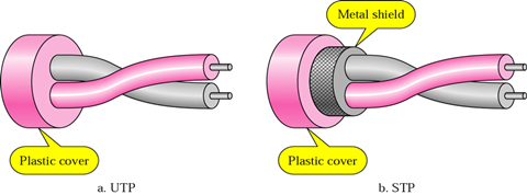
Twisted pair cable is a type of wiring in which two conductors of a single circuit are twisted together. It comes in two versions: Shielded Twisted Pair (STP) and Unshielded Twisted Pair (UTP). STP is commonly used in Token Ring networks and UTP is in Ethernet networks. The image below displays what UTP (left) and STP (right) look like.
A fiber optic cable is a cable containing one or more optical fibers. Fiber optic cables often contain several silica cores, and each fiber can accommodate many wavelengths (or channels), allowing fiber to accommodate ever-increasing data capacity requirements. When terminated with LC/SC/ST/FC/MTRJ/MU/SMA connectors on both ends, such as LC-LC, LC-SC, LC-ST, SC-ST, SC-SC, ST-ST etc, fiber optic cables can achieve fiber link connection between equipment.
Coaxial cable can be installed easily, relatively resistant to interference. However, it is bulky and just ideal for short length because of its high attenuation. It would be expensive over long-distance data transmission. By contrast, twisted pair cable is the most flexible and cheapest among three kinds of cables, easy to install and operate. But it also encounters attenuation problem and offers relatively low bandwidth. In addition, it is susceptible to interference and noises. As one of the most popular mediums for both new cabling installations and upgrades, including backbone, horizontal, and even desktop applications, fiber optic cable is small in size and light in weight. Because the conductor is glass which means that no electricity can flow through, fiber cable is immune to electromagnetic interference. The biggest advantage of fiber optic cable is that it can transmit a big amount of data with low loss at high speed over long distance. Nevertheless, it needs complicated installing skills, difficult to work with and expensive in the short run.
When selecting which kind of cable is appropriate for network services, one should keep in mind that each cable has its unique advantages and disadvantages concerning about these factors: cost, speed, security, reliability, bandwidth, data carrying-capacity, and so on.
Choosing among coaxial cable, twin-ax cable, twisted pair cable and fiber optic cable depends on your needs. You can balance the cost and the requirements of bandwidth to make a choice. In Fiberstore, you can find twisted pair cables and a series of fiber optic cables. Other cables, such as active optical cable (AOC) (eg. QSFP-4X10G-AOC10M) are also available for your networks. You can visit Fiberstore for more information about cable-based solutions.
Posted by: fernxu123 at
04:02 AM
| No Comments
| Add Comment
Post contains 639 words, total size 6 kb.
February 03, 2016
The increased deployment of 10 Gigabit Ethernet (GbE) infrastructure, coupled with the growing applications of bandwidth-demanding network services, drives the need for dense 40GbE switching. High-density 40G switches, such as Arista QSFP-40G Universal transceivers, are the available ports enabling the easy 10G to 40G migration. How much do you know about this Arista QSFP-40G Universal transceiver? This text will guide you to delve into this 40G QSFP+ transceiver.
The Arista QSFP-40G Universal transceiver is a pluggable optical transceiver in an industry standard QSFP+ form factor that can operate with both duplex multi-mode fiber (MMF) and single-mode fiber (SMF). It has four channels of 10G multiplexed inside the module, giving an aggregated 40G bandwidth over 2 strands of fibers. It’s called Universal owing to its ability to communicate with both MMF and SMF without the need for any software/hardware changes to the module or any additional hardware in the network. Here is a picture of Arista QSFP-40G Universal transceiver listed on Fiberstore.

The Arista QSFP-40G Universal transceiver uses a duplex LC connector, and operates on a wide range of fiber optic cables, including OM3 and OM4 MMF and SMF, realizing 150m reach on OM3 and OM4, 500m on SMF. It’s defined to the IEEE 40GBASE-LR4 standard, interoperable with QSFP-40G-LR4 and QSFP-40G-LR4L for distances up to 500m, compliant to the QSFP+ MSA SFF-8436 which defines the specification for QSFP optics. When migrating from 10G to 40G, the existing fiber patch cords, panels, trunks and cabling systems can be used without requiring a redesign or expansion of the fiber network, thus avoiding adding cost or complexity to the migration.
Arista QSFP-40G Universal transceiver addresses several challenges met in data center, and it boasts of the following advantages.
Since the existing multi-mode 40GbE solutions need the use of 8 fibers for a 40G link, users have to add additional fibers to increase the number of 40G links with other 40G QSFP+ optics. But by utilizing Arista QSFP-40G Universal transceiver, users increase the number of 40G links by 4X without making any changes to their fiber infrastructure. More specifically, with the Arista QSFP-40G Universal transceiver for the same number of 40G links as 10G links, there is no need to change fiber termination, nor to upgrade patch panels or trunks, but still the network scale and performance are expanded.
Besides, Arista QSFP-40G Universal transceiver is designed for both MMF and SMF, leading to simplified operations. Its interoperability with IEEE 40GBASE-LR4 and 40G-LRL4 allows easy connection to third party routers and switches in existing networks. Take JG661A for example, this HP product is exactly a 40GBASE-LR4 QSFP+ transceiver designed to run over SMF with duplex LC connector.
Additionally, this kind of 40G QSFP+ transceiver supports Digital Optical Monitoring (DOM) for link quality monitoring. DOM provides access to real-time operating parameters of the transceiver through a digital interface. It enables pro-active monitoring of the key parameters of the transceiver, helping network operators to become aware of degrading fiber paths, to detect transceiver problems and to test splicing/patching work remotely and in a non-intrusive way.
Arista QSFP-40G Universal transceiver offers a very cost-effective connectivity solution for data centers to migrate from 10 Gigabits/s to 40Gigabits/s with minimal disruption within existing multi-mode or single-mode infrastructure. As an excellent fiber optics products manufacturer and supplier, as well as a third party, Fiberstore supplies many Arista QSFP-40G-UNIV transceivers which are 100% compatible the original Arista QSFP-40G Universal transceivers. In addition, Fiberstore also offers 40G QSFP+ transceivers compatible with other major brands, including Cisco, Juniper and HP (eg. HP QSFP+). For more information about 40G QSFP+ transceivers, you can visit Fiberstore.
Posted by: fernxu123 at
02:43 AM
| No Comments
| Add Comment
Post contains 629 words, total size 5 kb.
February 01, 2016
Single-mode fiber (SMF) cables support advanced network applications required in data centers, enabling guaranteed performance for Gigabit applications. SMF can be categorized into OS1 and OS2. That is, OS1 and OS2 are cabled SMF specifications. For many people, one of the confusing aspects in fiber optics industry may contribute to the standardization, since several standards may be specified under one fiber cable type, just as SMF. Actually, the differences between OS1 and OS2 specifications are a little obvious. This text will explain the differences between OS1 and OS2.
The table listed below is about OS1 and OS2 specification differences.
| Name | OS1 | OS2 |
| Standards | ITU-T G.652A/B/C/D | ITU-T G.652C/D |
| Cable Construction | Tight-buffered | Loose tube |
| Maximum Attenuation | 1.0 db/km | 0.4 db/km |
| Maximum Transmission Distance (in 10GbE) | 2 km | 10 km |
| Application | Indoor | Outdoor |
First introduced in the year 2002, OS1 refers to a very old specification for SMF. The mechanical, optical and environmental characteristics of OS1 are compliant with ITU-T G.652A or ITU-T G.652B (IEC 60793-2-50 Type B1.1). Additionally, the low water peak fibers categorized in ITU-T recommendations as G.652C and G.652D also come under OS1 fibers. To put it simply, OS1 is a general term used to specify SMF that comes under the ITU-T G.652. Or in another way, OS1 covers all the SMFs that comply with ITU-T G.652 characteristics. In contrast, OS2 was introduced in the year 2006. Only G.652C and G.652D come under OS2, meaning that OS2 SMFs are low water peak fibers only.
OS1 is tight-buffered cable construction, appropriate for indoor applications, such as campus or data centers. On the contrary, OS2 is loose-tube cable construction, suitable for outdoor applications, including street or underground.
OS1 or OS2 fiber optical performance is discussed mainly from their attenuation and transmission distance. As for OS1 operating between 1310 nm and 1550 nm, its maximum attenuation allowed per km for an installed cable is 1.0 db, with the maximum transmission distance reaching 2 km at 10 Gigabit Ethernet (GbE) transmission. When concerning about OS2, maximum attenuation allowed per kilometer is 0.4db between 1310 nm and 1550 nm, allowing the maximum transmission distance of 10 km at 10GbE. As far as 40GbE transmission is concerned, the maximum distance of SMF is 40 km. For example, QSFP-40G-ER4, a Cisco 40GBASE-ER4 transceiver, takes SMF as its transmission medium for 40G links. The image below shows this Cisco QSFP-40G-ER4 module listed on Fiberstore.

OS2 SMFs can’t be connected with OS1 SMFs. If they are connected, unpredicted signal performance at water peak region would occur. So, it you want to use SMFs for your indoor applications, then choose OS1. For outdoor cases, OS2 is optimized. Besides, when the required transmission distance is less than 2 km, it’s wise to choose OS1 SMF, since OS1 is able to meet this requirement while costing less than OS2 SMF.
According to what have been discussed above, the confusion between these OS1 and OS2 specifications has been cleared off. Fiberstore offers various fiber optical products, including these OS1 and OS2 SMFs of high quality. In addition, Fiberstore also supplies fiber optic transceivers which are fully compatible with some major brands, such as Brocade QSFP+. You can visit Fiberstore for more information about OS1 and OS2 SMFs as well as the related fiber optic transceivers.
Posted by: fernxu123 at
03:40 AM
| No Comments
| Add Comment
Post contains 571 words, total size 5 kb.
January 29, 2016
Has the Linux Foundation, the most powerful nonprofit organization in the open source world, sold out to corporate interests? And how committed is it to defending the GPL free software license? Those are questions some critics are asking in the wake of recent changes to the Linux Foundation’s by-laws.
As former Red Hat (and current CoreOS) employee Matthew Garrett first noted, the Linux Foundation in mid-January modified its by-laws so that individual members of the organization can no longer participate in elections for the organization’s board of directors.
Since the other members of the organization consist of corporations, this means people who are not associated with a big company can’t help decide who gets to run the Linux Foundation.
In some ways, this change would seem relatively minor. It’s not as if the Linux Foundation is now only allowing corporations to join, or excluding non-corporate viewpoints entirely.
But Garrett speculates that the change was made to prevent Karen Sandler, executive director of the Software Freedom Conservancy and a staunch supporter of software freedom, from succeeding in her recently announced election bid for the Linux Foundation board. Sandler’s organization is currently enmeshed in a legal battle against VMware over claims that the company violated the terms of the GPL, the license that governs the open source code of Linux and many other major open source projects.
The Linux Foundation has issued relatively little public commentary on this issue. It’s still not clear whether the by-law change would prevent Sandler from running for the board, or just change the way other individual members of the Linux Foundation participate in board elections.
And it’s not even certain that the timing of the change and Sandler’s candidacy announcement was more than coincidental — although the Linux Foundation has not denied as much. The by-law change was made Jan. 15 and Sandler announced her candidacy Jan. 17.)
All the same, it seems unlikely that the Linux Foundation would risk so much face in the mere interest of providing a small, mostly symbolic help to VMware in its ongoing legal battle. The companies represented by the current board are hardly all in bed with VMware. The Foundation has much more to lose by seeming to be favoring corporations over the open source community writ large than it does by angering VMware, a company that deals mostly in closed-source software and has no singular influence over the Linux kernel.
If the by-law change was related to Sandler, I suspect the Linux Foundation’s strategy is simply to avoid setting a precedent of making it easy for activists to assume a leading role in the organization. That move would still have implications for how the Foundation balances the interests of well-funded companies with those of community organizations like the one Sandler heads. But it wouldn’t be proof that the Linux Foundation is out to get the Software Freedom Conservancy for its campaign against VMware, or that it wants to protect VMware’s interests more than those of the open source community as a whole.
Originally published at http://thevarguy.com/open-source-application-software-companies/has-linux-foundation-sold-out-vmware-probably-not
Posted by: fernxu123 at
03:27 AM
| No Comments
| Add Comment
Post contains 517 words, total size 4 kb.
January 27, 2016
Nowadays, data centers are witnessing a rise in the number of network connections, and it’s necessary for data centers to achieve even higher-density in both ports and cabling to accommodate the bandwidth demands. Parallel optics combining the use of cables and fiber optics serve as the medium to satisfy the growing need for transmission speed and data volume.
Multi-fiber connectors bring together 12 or 24 fibers in a single interface just as compact as a RJ45 connector. The multi-fiber push-on or also multi-path push-on (MPO) technology and especially the MTP connectors from the manufacturer US Conec have proven themselves as a practical solution for high-performance data networks in data centers. This paper mainly introduces MPO/MTP technology, and parallel optics which utilizes this multi-mode connectors in 40 Gigabit Ethernet (GbE) transmission.
Before going into the main body, a table showing the 40GbE standard, cable types and maximum allowable distances is below.
| Transmission technology | Cable type | Signal Rate | Maximum distance |
| 40GBASE-KR4 | PCB (bus) | 4 x 10 Gb/s | 1 m |
| 40GBASE-CR4 | Copper, Twinax | 4 x 10 Gb/s | 7 m |
| 40GBASE-SR4 | OM3, OM4 | 4 x 10 Gb/s | OM3 100m, OM4 150m |
| 40GBASE-LR4 | Single-mode Fiber | 4 x 10 Gb/s | 10 km |
As is shown in the table, while establishing 40GbE links, parallel optical channels with multi-mode fiber (MMFs) of the categories OM3 and OM4 are used. The ports have to accommodate four or even ten times the number of connectors. This large number of connectors can no longer be covered with conventional individual connectors, which explain the reason why the 802.3ba standard incorporated the MPO multi-fiber connector for 40GBASE-SR4 and 100GBASE-SR10. It can contact 12 or 24 fibers while saving space.
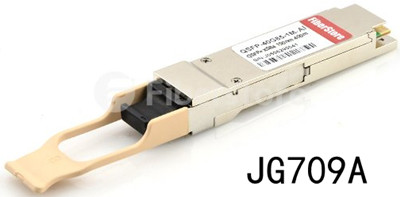
IEC 61754-7 and TIA/EIA 604-5 defined MPO connector that can accommodate up to 72 fibers in the tiniest of spaces, most commonly used for 12 or 24 fibers. This MPO connector is designed for the high-density connection of MMFs, allowing easy connection and disconnection. MPO connector has two alignment pins to align the ferrule, and a clamp spring. When closed, the MT connector is extremely compact and is thus well suited for high-density fiber connection within closures or cabinets. The kind of multi-mode connector combines high-density connection with convenient disconnecting action, ideal in satisfying the need for high-density packaging in equipment. In 40G links, QSFP+ transceivers use MPO connectors as the interface for high performance. Just like, this HP JG709A 40GBASE-CSR4 QSFP+ transceiver listed on Fiberstore achieves 300m link length with MPO connector.
Category OM3 and OM4 MMF are the future-proof cabling choices for 40G links. Lasers are used for OM3 and OM4. These lasers are generally vertical-cavity surface-emitting lasers (VCSELs) which are cheaper than distributed feedback lasers. The VCSELs are able to transmit data at higher rates. According to the table shown above, OM3 has a link length of 100 meters so it supports about 85 percent of all data center channels depending on architecture and size, and OM4 fibers have a link length of 150 meters so they cover nearly 100 percent of the required reach.
As noted in the table, the 802.3ba standard defines the parallel operation of four OM3/OM4 fibers for 40GbE in 40GBASE-SR4. Two fibers have to be used per link because this arrangement is full duplex operation, i.e. Simultaneous transmission in both directions. Therefore the number of fibers increases to eight for 40GBASE-SR4. That is four of the twelve fibers remain unused and eight of the twelve fibers are used in each case in connection with 12-fiber and MPO connectors. In the parallel optical link, the signal is split, transmitted over separate fibers and then joined again. That means the individual signals have to arrive at the receiver at the same time.
MPO/MTP technology is performance- and quality-assured as a trend for decision makers in to carefully plan their fiber optics infrastructure for 40GbE transmission. Fiberstore provides not only high-quality MPOMTP connectors, but also MPO-based patch cables (eg. Push-Pull MPO cable). You can visit Fiberstore for more information about MPO connectors and MPO-based cables.
Posted by: fernxu123 at
03:05 AM
| No Comments
| Add Comment
Post contains 695 words, total size 6 kb.
January 25, 2016
With each passing year, the demands for higher data rates and greater bandwidth in data centers grow. An increasing number of sophisticated fiber optical products have been introduced into the telecommunication market, including fiber patch cables (single-mode fibers (SMFs) and multi-mode fibers (MMFs)), with MMFs being preferred by users. MMFs have four types, OM1, OM2, OM3 and OM4. This article mainly details the differences between OM3 and OM4, helping you clear off the confusion of these two types.
The first thing to note is that OM4 is completely backwards compatible with existing OM3 systems. The connectors and termination of OM3 and OM4 are same. Besides, both OM3 and OM4 are Laser Optimised Multi-mode Fiber (LOMMF) share the same fiber core size of 50/125. So, what are the differences between them?
OM4 differs from OM3 mainly in their attenuation and dispersion provided. Let’s first see the following table which shows the attenuation and dispersion of OM3 and OM4.
| Type | Maximum Attenuation at 850nm | Minimum Fiber Bandwidth at 850nm |
| OM1 | 3.5 dB/Km | 2700 megahertz*Km |
| OM2 | 3.0 dB/Km | 4700 megahertz*Km |
- Attenuation Analysis
OM4 cable has lower attenuation than OM3. Attenuation refers to the reduction in power of the light signal as it is transmitted (dB). It’s caused by losses in light through the passive components, such as cables, and connectors, relatively simple to explain. The maximum attenuation at 850nm permitted by OM3 is less than 3.5 dB/Km, while the OM4 is less than 3.0 dB/Km. OM4 causes fewer losses.
- Dispersion Analysis
Dispersion is the spreading of the signal in time due to the differing paths the light can take down the fiber. Two types of dispersion are available: chromatic and modal. Chromatic is the spreading of the signal in time resulting from the different speeds of light rays, while modal is the spreading of the signal in time resulting from the different propagation modes in the fiber. Here the focus is put on the modal dispersion. The modal dispersion determines the modal bandwidth that the fiber can operate, and this is what the difference between OM3 and OM4 lies in. The minimum fiber bandwidth at 850nm allowed by OM3 is 2700 megahertz*Km, by OM4 is 4700 megahertz*Km, meaning that OM4 can operate at higher bandwidth.
- Other Considerations Between OM3 and OM4
OM4 is more network reliable than OM3, providing great design flexibility. What’s more, OM4 is able to reach an additional 60% links in the core-to-distribution and in the access-to-distribution channels compared to OM3 in 40G/100G Ethernet applications. In 40G Ethernet transmission using 40G QSFP, OM4 enables 150m length reach. Like Arista QSFP-40G-SR4, this 40G QSFP, when runs over OM4, enables 150m reach with MTP/MPO connector at a data rate of 40 Gbps. The image below shows what the Arista QSFP-40G-SR4 transceiver looks like.

On the one hand, since OM3 are compatible with OM4, these two types are interchangeable when the transmission distance limitations are accessible. But on the other, the additional bandwidth and lower attenuation of OM4 make it more ideal for MMF cabling infrastructure. Whether use OM3 or OM4 for your network, it depends on the specific situations, like cost, and distance required.
After detailed discussion, you may have gained a better understanding of the OM3 and OM4 differences and you can quickly choose MMF types to meet your higher bandwidth system requirements. Fiberstore OM3 and OM4 provide solutions that allow more effective and bandwidth-providing network installations. Besides fiber patch cables, Fiberstore also offers copper cables for your networks, such as QSFP-H40G-CU5M. This Cisco QSFP-H40G-CU5M product listed on Fiberstore is 100% compatible with the equivalent Cisco direct attach copper cables. For more information about fiber patch cables and copper cables, you can visit Fiberstore for more information.
Posted by: fernxu123 at
06:57 AM
| No Comments
| Add Comment
Post contains 637 words, total size 6 kb.
January 22, 2016
ADTRAN says more than 60 telecom service providers across six continents have utilized G.fast broadband solutions.
BT, the telecom operator in the UK, is one of the telecoms to conduct G.fast trials. The BT trials in Huntingdon, Cambridgeshire, reaching over two thousand premises are the latest to include the ADTRAN 500G Series G.fast solutions.
G.fast broadband technology is allowing carriers to deliver up to five times the broadband speed currently offered by the most progressive UK cable providers.
The company claims that ADTRAN solutions are changing the way broadband is transmitted, moving from more costly FTTP deployment models to emerging Fiber-to-the-distribution point (FTTdp) models and now Fiber-to-the-Cabinet (FTTCab).
This, coupled with ADTRAN’s intention to increase the port density of G.fast equipment in the future, offers potential savings for large service providers for every 50 meters of additional customer reach.
"Providing fiber to every home or business in a given community can be a logistical and financial challenge. Rather than relying on fiber for the entire network, G.fast solutions such as ADTRAN’s utilize existing copper assets for the last step of the journey,†said Mike Galvin, managing director of service, strategy & operations at BT.
"This allows us to provide the ultra-fast broadband that customers demand, while reducing the time and cost of running fiber all the way to the premises,†said Galvin.
Eduard Scheiterer, senior vice president, research and development, ADTRAN, said the company’s continued investment in G.fast includes end-user service activation through reverse powering capabilities.
"We are also working with standards bodies like the Broadband Forum to develop open APIs and interfaces allowing simplified, rapid deployment into any broadband network, regardless of FTTx vendor or OSS incumbency,†said Scheiterer.
ADTRAN’s G.fast solutions support open Software-Defined Network (SDN) deployment models that ensure rapid plug and play deployment capability within the multi-vendor FTTx networks that exist today.
The broadband technology company claims over 100,000 sealed micro DSLAMs in FTTdp and FTTCab deployments to date.
Originally pubkished at www.telecomlead.com/telecom-equipment/adtran-says-60-telecoms-use-g-fast-broadband-solutions-66797
Posted by: fernxu123 at
09:30 AM
| No Comments
| Add Comment
Post contains 336 words, total size 3 kb.
January 21, 2016
The demand for higher speeds and greater bandwidth in the telecoms network is increasing at a breathtaking rate. In order to accommodate this demand, there requires a need to upgrade to 40G Ethernet links for switch to server and storage area network connections in data centers. This upgrading to 40G links ushers the widespread use of Finisar QSFP+ optics. This article discusses Finisar QSFP+ optics in details.
Finisar's broad product selection and innovative technology have attracted many consumers, and it has become an optical module manufacturer for some major networking equipment vendors worldwide. Finisar QSFP+ optics are capable of distances ranging from very short reach within a data center to campus, access, metro, and long-haul reaches. They feature outstanding performance over extended voltage and temperature ranges, while minimizing jitter, electromagnetic interference (EMI) and power dissipation. In a word, Finisar QSFP+ optics demonstrate themselves as the ideal choices for your Internet services.
Finisar QSFP+ supports highly reliable operations in data center networks, optimized for Finisar switching platforms. With rigorous qualification and certification testing, these hot-pluggable QSFP+ form factors enable high-speed data connectivity for networking applications. Here two Finisar QSFP+ are introduced: FTL4C1QE2C and FTL410QE1C.
40GBASE-SR4 QSFP+ Transceiver (FTL4C1QE2C)Finisar's FTL4C1QE2C QSFP+ transceivers, compliant with the QSFP+ MSA and IEEE 802.3ba 40GBASE-SR4, are designed for use in 40G links over a single mode fiber (SMF) with the maximum link length of 10km. Fiberstore compatible Finisar FTL4C1QE2C, designed with built-in digital diagnostic functions, supports 41.2 Gb/s aggregate bit rates with duplex LC receptacles.

Similarly, Finisar's FTL4C1QE1C QSFP+ transceivers are also intended for use in 40G links over SMF. They feature a microprocessor and a diagnostics interface that provide performance information on the data link. These digital diagnostics functions help consumers monitor - in real-time - received optical power, transmitted optical power, laser bias current, transceiver input voltage and transceiver temperature of any transceiver in the network. These transceivers serve as the cost-effective tool for reliable performance monitoring.

Finisar 40G QSFP+ cables allow for great reliability and high performance. Finisar’s active optical cables (AOCs) accelerate data connectivity for storage, networking and high performance computing applications. Key advantages of Finisar’s AOCs include low weight for high port count architectures; small bend radius for easy installations; and low power consumption enabling a greener environment, thereby providing the lowest total cost solution for data centers. Quadwire, a 4-channel parallel AOC product, supports data center link lengths up to 100 meters for 40G links. It’s available in a point-to-point configuration using MSA compliant QSFP+ modules on each end, or a fan-out configuration with a QSFP+ module on one end and four separate SFP+ modules at the other end.
Finisar QSFP+ optics ensure system reliability after experiencing the rigorous qualification and certification testing, providing state-of-the-art performance with optimized Finisar solutions, and also eliminate issues related to transceiver incompatibility. With Finisar QSFP+ optics, it’s easy to carefully plan optical fiber network solutions, which deliver lower cost, consistent high performance, and pay-as-you-grow flexibility. With Finisar QSFP+ optics, you can go on network performance monitoring easily.
Finisar QSFP+ optics make flexible and simple 40G connectivity possible, while saving your money. You can try them. Fiberstore, as a professional manufacturer and supplier for optical fiber products, offers various Finisar QSFP+ optics with high quality and low cost, such as FTL4C1QE2C and FTL410QE1C mentioned above. Want to know more information about Finisar QSFP+ optics, you can visit Fiberstore.
Posted by: fernxu123 at
03:14 AM
| No Comments
| Add Comment
Post contains 594 words, total size 5 kb.
January 19, 2016
Along with the development of fiber technologies over the past a couple of years, tools for easier fiber connection have been invented—fiber optic connectors (or so-called "better mousetrapâ€). Given there are various fiber optic connectors (eg. ST, SC, LC, MPO/MTP) available for network designers to set up fiber connectivity in bandwidth-demanding applications, this article introduces MPO/MTP in details.
MPO/MTP technology with multi-fiber connectors ensures ideal conditions for establishing high-performance and high-speed data networks to handle bandwidth requirements. The term MTP is a registered trademark of US Conec used to describe their connector. The US Conec MTP product is fully compliant with the MPO standards. As such, the MTP connector is a MPO connector. The following passages will mention MPO only instead of MPO/MTP for simplicity.
To let readers gain a better understanding of MPO technology, MPO components introduction goes first followed by the applications of MPO technology.
MPO (multi-position optical) connector contains up to 24 fibers in a single connection. It’s available in a male version (with pins) or a female version (without pins). The pins ensure that the fronts of the connectors are exactly aligned on contact and that the endfaces of the fibers are not offset. MPO connector components mainly contain two parts: adapter and cable.
MPO AdaptersThere are two types of MPO adapters based on the placement of the key: key-up to key-down, and key-up to key-up. In the former type, the key is up on one side and down on the other. The two connectors are connected turned 180° in relation to each other. In the latter type, both keys are up. The two connectors are connected in the same position in relation to each other. Just like what’s shown in the figure below.

MPO fiber cables are available in two primary types: MPO trunk cables and MPO harness cables.
MPO trunk cables are available in 12-144 counts. They serve as a backbone connecting the MPO modules to each other, intended for high-density applications.
MPO harness cables, also called MPO breakout cables or MPO fanout cables, are available in 8-144 counts. As terminated with MTP/MPO connectors on one end and standard LC/FC/SC/ST/MTRJ connectors (generally MTP to LC) on the other end, MPO harness cables provide a transition from multi-fiber cables to individual fibers or duplex connectors.
The remaining parts describe how MPO technology is utilized to permit successful migration from 10 GbE to 40/100 GbE.
It’s no doubt that converting or expanding existing infrastructure to accommodate higher bandwidth applications is more ideal and practical in data centers. In 10 GbE to 40 GbE/100 GbE migration, the most key point that should be kept in mind is the capacity expansion in which MPO modules are used to enable faster transmission. Many 40G QSFP transceiver modules utilize MPO technology for 40G links, among which the Cisco QSFP is the most widely-used module. Take Cisco for example, QSFP-40G-SR4 realizes 40G links over 850nm multi-mode fiber (MMF) with MPO-12 as its connector type.

In 40G to 100G migration, there requires the use of 24-fiber MPO cables. The existing 12-fiber connection can either be expanded with the addition of a second 12-fiber connection or can be replaced with the installation of a 24 fiber connection.
With these MPO components and technology applications, it’s easier for network designers to select the right MPO types to meet the bandwidth requirements. As a professional fiber optical product manufacturer and supplier, Fiberstore supplies various MPO modules and cables, including QSFP-40G-SR4 (one of Cisco QSFP products) mentioned above. You can visit Fiberstore for more information about MPO modules.
Posted by: fernxu123 at
03:00 AM
| No Comments
| Add Comment
Post contains 610 words, total size 5 kb.
January 16, 2016
The operators of the Southern Cross Cable Network say they have added 900 Gbps of capacity to their submarine network. The upgrade raises the undersea fiber-optic network's total network lit capacity to 5.8 Tbps. Meanwhile, the company also has improved its packet transport capabilities to enhance Carrier Ethernet service delivery.
Both initiatives benefited Ciena Corp. (NYSE: CIEN), which is the Southern Cross Cable Network's primary optical transport systems supplier. The Ciena 6500 is the workhorse optical platform for the submarine cable network (see, for example, "Southern Cross submarine fiber network jumps to 100G"). However, Ciena also delivered enhanced technology for other systems it has supplied for the network.
"While we have augmented our transmission by 900 Gbps per segment, we have also upgraded our key Ciena 5430 nodes to 15-Tbps OTN switching capability, a first for the region and a world first for a submarine cable operator as far as we are aware," detailed Southern Cross President & CEO Anthony Briscoe. "Southern Cross' key switching nodes are now capable of switching over 100 times Southern Cross' original segment capacity.
"Our latest expansion has also deployed Ciena's 200-Gbps per wavelength technology across our Hawaiian inter-island network in another world-first in technology activation, as well as continuing to leverage Ciena's flexible grid, GeoMesh, and 8D-2QAM technologies to maximize capacity and resiliency within our network while ensuring operational simplicity, scalability, and evolution toward software-defined networking (SDN)," Briscoe added.
Meanwhile, Southern Cross has decided to install the Ciena 8700 Packetwave packet switching platform as well. The systems will help the operator provide MEF CE2.0 compliant Carrier Ethernet packet transport services at data rates from 1 Gbps to 100 Gbps.
"Along with our existing key Internet data center access points such as Equinix in Sydney, CoreSite in San Jose, and the Westin Building in Seattle, these developments cement the Southern Cross position as the only single system provider of highly resilient innovative international capacity solutions between key data locations in Australia, New Zealand, the USA, and Fiji," asserts Southern Cross CTO Dean Veverka.
These recent upgrades, paired with previous enhancements, have extended the network's lifetime to at least 2030 while giving it a potential capacity of 14 Tbps, Southern Cross adds. Further network enhancements are likely, Briscoe indicates.
Originally published at www.lightwaveonline.com/articles/2016/01/southern-cross-adds-capacity-enhances-packet-transport.html
Posted by: fernxu123 at
02:57 AM
| No Comments
| Add Comment
Post contains 384 words, total size 3 kb.
January 15, 2016
Driven by the enormous rise in networking access devices and applications, the total bandwidth requirements are also growing accordingly. Networking devices are needed to accommodate the higher port density. To meet these demands, several cabling solutions have been developed by network designers. Commonly used cabling options include fiber optic cables, direct attach cables and active optical cables. Of course, there also exist some other cabling solutions, like copper RJ45. But this article gives detailed information about the former three.
Fiber optic cables are primarily divided into two types based on transmission media: single-mode fiber (SMF) and multi-mode fiber (MMF).
Single-Mode Fiber—SMF, usually in yellow, has a small 8-10 micron glass core and one pathway of light, leading to the more focused light toward the center of a core instead of bouncing it off the edge of the core like MMF. Therefore, SMF is more suitable for transmitting data over longer distances, typically used in long-haul network connections when combined with transceivers. Take QSFP-40G-LR4 for example, this Fiberstore QSFP-40G-LR4 module compatible with Cisco can realize 10km link lengths when running over SMF. The figure below shows what a QSFP-40G-LR4 transceiver looks like.

Multi-Mode Fiber—MMF, usually in orange, has a larger core and more pathways of light. With multiple pathways of light, MMF can gather more light and signals than single-mode ones within shorter distances. The typical applications of MMF include general data and voice fiber, such as bringing finer to the desk, and alarm system.
Direct attach cable (DAC), a kind of optical transceiver assembly, is a form of high speed cable with "transceivers†on either end used to connect switches to routers or servers. The "transceivers†on both ends of DACs are not real optics and their components are without optical lasers. This term, DAC, is used for copper cables that can be of the passive or active type. Nowadays, direct attach copper cables still have wide applications in telecommunications, especially in 40Gigabit links, owing to their interchangeability, low cost and fast data rates. Like direct attach passive copper cable, Cisco QSFP-H40G-CU3M product is just the QSFP to QSFP direct attach passive copper cable assembly designed for 40 Gigabit links. This QSFP-H40G-CU3M product listed on Fiberstore offers you a cost-effective solution for short solution.

Active optical cable (AOC) is a cabling technology that accepts same electrical inputs as a traditional copper cable, converts the electrical signal to the optical signal—known as an electrical-to-optical conversion (i.e. E/O) in the transceiver assembly. That is to say, AOC uses electrical-to-optical conversion on the cable ends to improve speed and distance performance of the cable while mating with electrical interface standard.
With these detailed information about cabling solutions, it’s easier for you to find what kind of cabling solution you choose to build and expand your existing networking infrastructure, so as to increase bandwidth and ensure you good network performance. Fiberstore is a leading manufacturer and supplier of fiber optical products, including cabling assembly structured in both fiber and copper, like QSFP-H40G-CU3M mentioned above. You can choose the cost-effective cabling option for networking connectivity according to specific situations at Fiberstore. Please not hesitate to contact us when you come into any puzzle or question!
Posted by: fernxu123 at
03:03 AM
| No Comments
| Add Comment
Post contains 546 words, total size 5 kb.
January 13, 2016
Today’s data centers have witnessed an unprecedented increase in computing bandwidth which is needed to drive network services, causing the never-ceasing evolution of Ethernet technologies to accommodate this high bandwidth need. And during this evolution, fiber optic cables are always preferred by users in network deployment for their longer link lengths and greater capacity, compared with their counterpart copper cabling solutions. Here, three key points are mentioned before establishing fiber optic links for your network performance, like fiber optic construction, fiber principles, and versus among different cable types.
Fiber optic cable is a cable made of glass and capped at either end with connectors. It cannot bear sharp bending or longitudinal stress because of its glass material. Thus, special construction techniques are used to allow the fiber to move freely within a tube. Usually fiber optic cables contain several fibers, a strong central strength member, and one or more metal sheaths for mechanical protection (image shown below). Some cables also consist of copper pairs for auxiliary applications. These cables are featured with low insertion loss and return loss, high durability (more than 500 times mating), as well as temperature stability (operating temperature: -20 to +75 ℃). For these characteristics, fiber optic cables are one of the fastest-growing transmission media in optical network systems.

Fiber optic cables’ delicacy and great ability to carry light over either short or long distances are owing to some fundamental physics concerning refraction and reflection of light. Since there exists differences in speeds that the light can travel through different materials, whenever a ray of light passes from one transparent medium to another, the light is affected by the interface between the two materials. Each material can be described based on its refractive index, which is the ratio of the speed of light in the material to its speed in free space. This relationship between these two refractive indexes determines the critical angle of the interface between the two materials.
Fiber optic cables are available in different types, such as breakout cable and distribution cable, indoor cable and outdoor cable.
Breakout Cable/Distribution CableBreakout cables are made of several simplex cables bundled together. These cables are used to carry fibers that have individual connectors attached, rather than being connected to a patch panel. They are designed to provide the ease of connector installation on optical fiber. Their typical use in fiber optical systems is for 40Gigabit links. Like QSFP+ breakout cable (fiber version), the QSFP to 4x SFP+ breakout active optical cable assembly offers a cost-effective interconnect solution for 40Gigabit links. Take Cisco QSFP-4X10G-AOC10M for example, Fiberstore compatible Cisco QSFP-4X10G-AOC10M runs over breakout active optical cable (AOC) for 40G interconnection. The following figure shows what the QSFP-4X10G-AOC10M product looks like.

Distribution cables have several tight-buff er cables bundled under the same jacket. They can be directly terminated. However, because distribution cables are not individually reinforced, they need to be broken out with a "breakout box†or terminated inside a patch panel or junction box.
Indoor Cable/Outdoor CableIndoor or outdoor cable uses dry-block technology to seal ruptures against moisture seepage and gel-filled buff er tubes to halt moisture migration, suitable for aerial, duct, tray, and riser applications.
After discussion, maybe you have obtained a better understanding of fiber optic cables, which helps you to establish your fiber optic links. As a leading fiber optical product manufacturer and supplier, Fiberstore offers various kinds of fiber optic cables, including QSFP+ breakout cable mentioned above (available in both copper and fiber versions). For more information about fiber optic cables, you can visit Fiberstore.
Posted by: fernxu123 at
03:09 AM
| No Comments
| Add Comment
Post contains 614 words, total size 5 kb.
January 11, 2016
It’s no doubt that 10Gbps speeds for individual streams have been routinely reached under today’s networking environment. And for better network performance, the existing bandwidth has been generated to 40Gbps. Among various network devices designed for 40 Gigabit Ethernet (GbE) links, 40G QSFP+ transceivers are of vital importance in driving the bandwidth to a mounting point. Here this publication puts its focus on the Juniper 40G QSFP+ transceivers, which ensure high density and low latency, as well as small power consumption.
Firstly let’s figure out what is the 40G QSFP+ transceiver.
The Quad Small Form-factor Pluggable (QSFP) is a compact, hot-pluggable transceiver used for data communications applications. The 40G QSFP+ transceiver is a parallel fiber optical module, using four independent optical transmit and receive channels. It uses a 4 x 10Gb/s link configuration for a 40Gb/s port, offering users high-density 40 Gigabit Ethernet connectivity options for high-performance networks. QSFP+ transceivers can be applied in switches, routers and data center applications. Compared with SFP+ transceivers, QSFP+ transceivers increase the port-density by 3x-4x. Besides, they still enjoy the following features.
Juniper QSFP+ is a Multi-Source Agreement (MSA) for high speed application, such as 40G-BASE, which provide four channels of data in one pluggable interface. Each channel is capable of transferring data at 10Gbps and supports a total of 40Gbps. Juniper 40G QSFP+ transceivers enjoy the following listed key features:
- QSFP+ MSA, SFF-8436 Compatible;
- Four Independently Addressable Transmit and Receive Channels;
- Highly Compact and Electrically Hot-pluggable;
- Digital Diagnostic Monitoring (DDM) Interface for Better Module Management;
- Simplified Heat Management With Reduction in Power Consumption;
After discussion on several key features of Juniper 40G QSFP+ transceivers in general, here goes the detailed information about two types of Juniper 40G QSFP+ transceivers: Juniper 40G QSFP+ LX4 transceiver and Juniper 40G QSFP+ LR4 transceiver.
Juniper 40G QSFP+ LX4 TransceiverThe Juniper QSFP+ LX4 transceiver has four 10 Gbps channels, each of which can transmit and receive simultaneously on four wavelengths over a multi-mode fiber (MMF) strand. The result is an aggregated duplex 40 Gbps link over a duplex of two MMF strands. Using duplex LC connectors, QSFP+ LX4 connections can reach 100 meters on OM3 MMF or 150 meters on OM4 MMF. What’s more, this Juniper QSFP+ LX4 transceiver (JNP-QSFP-40G-LX4) addresses the challenges of fiber infrastructure by providing the ability to transmit full-duplex 40Gbps traffic over one duplex MMF cable with LC connectors. In other words, the Juniper QSFP+ LX4 transceiver, a short-reach optical transceiver that delivers 40Gbps over duplex OM3 or OM4 MMF, allows 40Gbps connectivity to connect directly to the 10Gbps fiber and fiber trunk.

For Juniper 40G QSFP+ LR4 transceiver, JNP-QSFP-40G-LR4 enables high speed 4 x 10G operations. It’s designed for use in 40 Gigabit Ethernet links over single mode fiber (SMF) with Duplex LC connectors. Compliant with the QSFP+ MSA and IEEE 802.3ba, JNP-QSFP-40G-LR4 is RoHS-6 compliant with built-in DDM interface. Fiberstore compatible Juniper JNP-QSFP-40G-LR4 is intended to support up to 10km over a standard pair of G.652 SMF.

The Juniper 40G QSFP+ transceivers are well suited for Infiniband, 40GBASE-SR4, 40GBASE-LR4 applications, suitable for short reaches among switches, routers and data center devices. Combined with right fanout cables, these modules can interface up to four SFP+ transceivers.
Juniper 40G QSFP+ transceivers boast of high-density features and provide users with 40Gbps connectivity for better network performances. Fiberstore supplies various Juniper 40G QSFP+ transceivers which are quality and performance assured, such as JNP-QSFP-40GE-LX4 and JNP-QSFP-40G-LR4 mentioned above. Please feel free to contact us for more information about Fiberstore 40G QSFP+ transceivers compatible with Juniper.
Posted by: fernxu123 at
03:25 AM
| No Comments
| Add Comment
Post contains 622 words, total size 6 kb.
32 queries taking 0.1116 seconds, 114 records returned.
Powered by Minx 1.1.6c-pink.

