



May 19, 2016
The number of cloud applications, virtualized workloads, coupled with a host of devices housed in data centers, all these increase at an amazing speed in this technological world. When walking past the data center, you may hear such a call for more capacity and greater performance from your servers. This call doesn’t slack with everyday passing, but it grows vigorously. In order to accommodate these applications that require higher data transport rates, it’s not advised to sit still for some enterprises. If your data center hasn’t shifted from 10Gbps to 40Gbps infrastructure, now it’s your chance by deploying 40GbE with BiDi QSFP+ optics (ie. Cisco QSFP-40G-SR-BD) at lower costs than using 40G QSFP+ optics.
BiDi stands for "bi-directionalâ€. This new BiDi optical technology is available only from Cisco. Cisco BiDi optics is a standard QSFP, MSA-compliant optical connector that can operate with any Cisco switch that supports QSFP modules and connects with any vendor’s standards-compliant equipment. It uses two different wavelengths on the same fiber, with one wavelength headed in one direction and the second wavelength traveling in the other direction.
BiDi technology uses specialized, multilayer, thin-film dielectric coating and lensing, which allows components to pass and reflect optical signals at the same time. And it uses Bidirectional Optical Sub-Assembly (BOSA) technology to support two wavelengths (20Gbps total) on each fiber. Each QSFP can deliver 40Gbps over the same duplex multi-mode fiber (MMF) cabling you use right now.
Inside this module, four channels each of 10Gbps signal transmission and reception are converted to two bidirectional channels of 20Gbps signals over two different wavelengths (usually 850nm and 900nm) respectively. BiDi optics represents a new solution to deploy 40GbE that meets all 40GBASE-SR4 performance criteria. The signal is sent to a target device via 850nm on one fiber. Then the signal from the target device is sent via 850nm on the other fiber. This also works for signals on 900nm, as is shown in the following image. To put it simply, BiDi provides 40GbE on two MMFs and duplex LC connectors, just like the existing 10G infrastructure that is deployed today.

With 40G BiDi, upgrading from 10G to 40G is much easier: to replace the existing 10G optical modules with 40G BiDi optical modules.
For instance, in 10GbE transmission, 10GBASE-SR optics uses two MMFs and duplex LC connectors for transmitting on one of the fibers and receiving on the other fiber. As for current 40GbE, 40GBASE-SR4 (eg. 40G-QSFP-SR4) uses four 10G lanes to support 40G through 12-fiber trunks and patch cords terminated with MPO connectors., with four for receiving, four for transmitting and the rest four fibers unused. This difference requires the change of infrastructure when upgrading 10G network to 40G network. If the 40G BiDi QSFP+ transceiver for short distance also using the duplex transmission mode, things would be much easier. That’s why choose 40G BiDi QSFP transceiver.

Besides, with 40G QSFP+ optics only using 8 of the 12 fibers in a 12-fiber trunk, this results in the disappearance of one third of the total bandwidth available to a data center when migrating from 10G to 40GbE. If select 40G BiDi QSFP+ optics, this bandwidth disappearance can be avoided, since only a pair of cables are used.
Just as what has been mentioned above, 40G BiDi transceiver modules give you 40Gbps over your existing 10Gbps cable plant, meaning that you can connect your top-of-rack switches using the same MMF and patch cables you are using right now, to get 40Gbps performance. If you were building a new 40Gbps data center fabric the traditional way, you would need to run 8 MMF strands between your access and aggregation layers. What a costly project. But with BiDi optics, there is no need for expensive 40G migration cassettes, and no need to add additional fiber infrastructure.
In an upgrading project, cost and time are the critical factors which should be considered. 40G BiDi optical modules offer another way to deploy 40G Ethernet: it’s less costly to implement 40G Ethernet using two MMFs (vs. the 8 fibers required by 40GBASE-SR4). With 40G BiDi optics, 40Gbps performance is no longer a luxury. With 40G BiDi optics, there is no need to rewire your data center to get the next level of capacity and performance. With 40G BiDi optics, it’s possible to upgrade capacity without having to upgrade cabling, a huge cost saving. Fiberstore supplies various 40G BiDi QSFP+ transceivers for your smooth 40G migration. You can visit Fiberstore for more information about 40G BiDi transceiver modules.
Posted by: fernxu123 at
02:44 AM
| No Comments
| Add Comment
Post contains 783 words, total size 6 kb.
May 17, 2016
The explosive data traffic which is driven by IP video and "cloud computing†demands for optimized solutions in data centers. Such solutions taken for higher speed data rates (say 100Gbit/s) are based on advanced transceiver technologies which are engineered to make use of the full bandwidth of fibers. These advances lower costs, increase efficiency, and make 100G applicable to a wider variety of carrier and data center applications. Nowadays, as 100Gbps transmission is becoming accessible, 100G optics hit the headline the time when they are brought to the market. Just similar to 10G interconnect solutions, there are also a set of different optical transceivers that are designed for 100G transmission, like CXP, CFP, CPAK, and QSFP28. This article mainly talks about the pluggable form-factor CFP and its later generations: CFP2, and CFP4.
When the IEEE 802.3ba committee ratified the 100 Gigabit Ethernet (GbE) standard, along with the general specification, and defined a number of fiber optic interfaces, the transceiver industry launched an alphabet soup of form factors. The CFP emerged first, "C" for 100, and FP for "Form factor, Pluggableâ€. Like the early versions of 10G transceivers, CFP optical transceiver form factor is huge, supporting data rates of 40 and 100Gbps. Aimed primarily at 40- and 100GbE applications, the CFP supports both single-mode fiber (SMF) and multi-mode fiber (MMF) and can accommodate a host of data rates, protocols, and link lengths.
The CFP multisource agreement (MSA) was formally launched at OFC/NFOEC 2009 in March by founding members Finisar, Opnext, and Sumitomo/ExceLight (now known as Sumitomo Electric Device Innovations USA following the merger of ExceLight and Eudyna Devices USA Inc..These founding members actually began meeting when the IEEE 802.3 Higher Speed Study Group (HSSG) was only focused on developing a standard for 100GbE. When that activity was expanded to include 40GbE in July 2007, the CFP MSA followed suit.

CFP form factor, as mentioned above, supports both SMF and MMF, as well as a variety of data rates, protocols, and link lengths, including all the physical media-dependent (PMD) interfaces encompassed in the IEEE 802.3ba Task Force, which was ratified in 2010. At 40GbE, target optical interfaces include the 40GBase-SR4 for 100 m and the 40GBase-LR4 for 10km. There are three PMDs for 100GbE: 100GBASE-SR10 for 100m, 100GBASE-LR4 for 10km (ie. CFP-100G-LR4), and 100GBASE-ER4 for 40km.
CFP form-factor enjoys several features which enable it to support a wide range of distances as well as various power dissipation. Firstly, its size is suitable for longer-reach interfaces and single-mode fiber applications. Technically, the CFP works with MMF for short-reach applications, but practically it is not really optimized in size for MMF market judging from its size, most notably because the MMF market requires high faceplatae density.
Secondly, the form factor includes a two-piece electrical connector. The connector itself features two rows, enabling improved density in its overall footprint.
The last point is that CFP is known as the riding heat sink, in which the heat sink is attached to rails on the host card and "rides" on top of the CFP, which is flat topped. The heat sink can be included or omitted depending on the thermal requirements of the host system. When included, the heat sink presses down on the module, providing a good conductive surface that is also low friction, making it very easy for the operator to insert the module into the host board.
CFP2, a new form factor specified by the CFP MSA, is also a hot-pluggable transceiver module that supports the IEEE 100GbE. Compared to the existing CFP, CFP2 is half the size of the CFP (image below) and consumes half the power. Besides, CFP2 doubles the front panel port density owing to integration of optics and ICs, and increase in electrical I/O rate from 10G to 25G.

CFP4 specifications document became available announced by MSA members in 2014. CFP4 enjoys the same features as CFP2 except that the CFP4 has a smaller size than CFP2. In addition, CFP4 quadruples front panel port density.
Pluggable CFP, CFP2 and CFP4 optical transceivers support the ultra-high bandwidth requirements of data communications and telecommunication networks that form the backbone of the Internet. CFP is widely available in the market, especially with the development of 100GbE in recent years. However, CFP2 and CFP4, due to the high cost of research and development, are still not so much widely available in the market.
100G CFP, CPF2 and CPF4 transceivers accelerate the data flow throughout your data centers, delivering significant reductions in power consumption. Fiberstore has a complete suite of 100G CFP transceivers (Cisco CFP-100G-LR4 mentioned above) for your 40G and 100G upgrading from 10G networks. Want to know more information about CFP optical transceivers and other 100G optics, you can visit Fiberstore.
Posted by: fernxu123 at
02:43 AM
| No Comments
| Add Comment
Post contains 806 words, total size 6 kb.
May 12, 2016
As one of the most effective approaches today for reliable and long-distance communications, fiber optic cable has attracted network designers’ notice while they take on cabling installation and upgrade projects. Undoubtedly, compared with copper, fiber optic cable delivers more bandwidth, and allows for more reliable data transmission over longer distance, say 10km distance is possible in GbE applications when used in combination with 1000BASE-LX SFP transceivers (EX-SFP-1GE-LX). To put it simply, fiber is able to carry more information with greater fidelity since finer is immune to many environmental factors that affect copper wire. However, there are many aspects that may influence the performance of fiber, such as light loss, a key issue. And such fiber light loss seems to be a top priority for network designers to consider while handling fiber optic cable. This article mainly discusses problems that cause loss and methods to fix it.
Before talking about fiber light loss, it’s imperative to have the basic knowledge about light loss.
Fiber optic signal is made of light, and when fiber optic cable carries these pulses of light between transmitters and receivers, signal loss occurs during transmission. In order to ensure the smooth data transmission, the light must arrive at the far end of the cable with enough power to be measured. Light loss between the ends of a fiber link results from multiple sources, such as the attenuation of the fiber itself, fusion splices, macro bends, and loss through adapter couplings where end-faces meet. Among these important sources that can bring a network down, dirty and damaged end-faces are the most underestimated threat. Dirty end-faces are a leading cause of fiber link failure for both installers and private network owners. Contaminated end-faces are likely to cause fault in fiber links. It’s easy to prevent, but there continues to be a lack of appreciation for this crucial issue and lots of misinformation about proper techniques.
In this passage, two sources that cause loss as light leaves one end-face and enters another inside an adapter are introduced: contamination and damage.
- Contamination
Contamination falls in many forms, from dust to oils to buffer gel. Simply touching the ferrule will immediately deposit an unacceptable amount of body oil on the end-face. Dust and small static-charged particles float through the air and can land on any exposed termination. This can be true in facilities which are under construction or renovation. In new installations, buffer gel and pulling lube can easily find its way onto an end-face.

As for such contamination, protective caps, also called "dust capsâ€, are one of the most common contributors. These caps are made in rapid production processes during which a mold release compound is used. Such compound is likely to contaminate end-faces on contact. What’s more, as the time goes by, the plastic cap becomes "oldâ€, and then plasticizers would deteriorate and result in an outgas residue. Last, airborne dust itself would find its way into the protective cap and move to the end-face when the cap is pushed onto a ferrule. It’s a very common mistake to assume that end-faces are clean when patch cords or preterminated pigtails are removed from a sealed bag with protective caps in place.
- How to Avoid Such Contamination?
To avoid this problem, it’s recommended to follow the following steps. Inspection of the end-face is necessary to verify that no containments are within the field of view. The most crucial area to clean is the core of the fiber, followed by the cladding. Yet contamination on the ferrule—outside of the end face—could slide towards to core as the fiber is mated or handled. Therefore, all visible contamination should be removed if possible.
- Damage
It’s ill-advised to mate every connection first and then inspect only those that fail, as the physical contact of mated contaminants can cause permanent damage. This permanent damage would lead to more costly and time-consuming determination or replacement of preterminated links.
Scratches, pits, cracks or chips all "belong to†damage. These end-face surface short comings could attribute to the poor termination or mated contamination. Regardless of the cause, damage must be evaluated to determine if action is required, as some of it can be ignored or remedied. Up to 5% of the outer edge of fiber cladding generally may be chipped; this is a common result of the polishing process. Any chips on the core are unacceptable. If scratches or excess epoxy bleed are found, re-polishing with fine lapping paper can eliminate the problem. If the end-face is cracked or shattered, the fiber must always be re-terminated.
- How to Prevent Such Damage?
In every step taken, all end-faces should be inspected before insertion. If a connector is being mated to a port, then the port should be inspected as well. Be aware that contamination inside a port can not only cause damage but also migrate to the connector being inserted. Too often equipment ports are overlooked not only as contaminated themselves but also as a source of contamination for test cords. So, it’s a wise approach to check every equipment port before they are safe and clean to be inserted.
It’s known that fiber light loss can affect the data transmission speed and distance. This distance further depends on wavelength, and cable types, ranging from 550m with multi-mode cable with GbE modules (eg. MA-SFP-1GB-SX) and up to 40km for single-mode cable 40GbE modules (ie. QSFP-40G-ER4).
To reduce fiber light loss as much as possible, it’s of great importance to keep fiber from being contaminated or damaged. Certainly, fiber light loss sources are not limited to above-mentioned two, the intrinsic fiber core attenuation also included. Hope this text is helpful for you to avoid possible external fiber contamination and damage, so as to improve fiber performance.
Posted by: fernxu123 at
02:40 AM
| No Comments
| Add Comment
Post contains 979 words, total size 7 kb.
May 10, 2016
In modern fiber optic networks, various tools and gadgets which are fundamental to performing smooth networking service have been designed with the latest fiber optic technology. Among these smart inventions, one particular device—fiber optic transceiver, attracts more and more subscribers’ attention. This device has two functions that it's both a transmitter and receiver which are combined to form a unit and use the same channels to send and receive data.
In optical communication networks, fiber optic transceivers are used to connect the cabling to the network, and provide interface between the equipment and the cabling. They can be found in many form factors for different Gigabit applications: like SFP, GBIC, XFP, SFP+, CFP, QSFP+, and so on. This article mainly talks about XFP transceiver used for 10 Gigabit Ethernet (GbE) networks.
XFP specification was developed by the XFP MSA (Multi Source Agreement) Group. It is an informal agreement of an industry group, not officially endorsed by any standards body. The first preliminary specification was published on March 27, 2002. And the first public release was on July 19, 2002. XFP was adopted on March 3, 2003, and updated with minor updates through August 31, 2005.
XFP transceiver is a little form factor hot pluggable component intended for 10G system applications. The recognized standard with this transceiver is called XFP MSA, which was created by various companies. XFP is often referred to as XFI. XFI electrical interface specification was a 10 gigabit per second chip-to-chip electrical interface specification defined as part of the XFP MSA.
XFP transceivers can be plugged into routers, switches, transport gear, or pretty much any network device to transmit and receive signals. They are protocol-independent and hot-swappable while the device is operating, standardized to be interchangeable among vendors, capable of operating over many different physical medium and at different distances. XFP is optical inter-operable with 10GBASE XENPAK, and 10GBASE X2 on the same link. Judging for its size, XFP packaging is smaller than the XENPAK form-factor, which is desirable by many designers. The smaller the footprint, the easier to design it into the systems when needed.

Being the first small form factor 10GbE optics, XFP meets the relation to MSA launched by various popular companies on the market today. There are many kinds of XFP transceivers available in the telecommunication market, including 10GBASE-SR XFP, 10GBASE-LR XFP, 10GBASE-ER XFP and 10GBASE-ZR XFP.
- 10GBASE-SR XFP
10GBASE-SR XFP (ie. XFP-10G-MM-SR) is designed to work through MMF using 850nm lasers. This XFP type supports a link length of 26m on standard FDDI-grade MMF. And when using 2000 MHz/km MMF (OM3), 300m link lengths are possible. Fiberstore compatible Cisco XFP-10G-MM-SR is able to realize 300m distance reach over OM3 with the maximum data rate at 10.3125Gbps.

- 10GBASE-LR XFP
10GBASE-LR XFP is intended to operate via SMF using 1310nm lasers. The maximum link length that XFP 10GBASE-LR port type can support is 10km when it’s used in combination with high-quality optics.
10GBASE-ER XFP is able to realize the maximum link length of 40km via 1550nm SMF, and 10GBASE-ZR XFP is capable of realizing the utmost distance of 80km also by 1550nm SMF.
To those 10GbE XFP transceiver subscribers, they can either go to the local store for choice or buy it online. The question is how to find a reliable seller who supplies high-quality products at affordable prices. One of the most most widely used and reliable brands of transceivers is Cisco. Before making a decision, it’s advised to read the reviews on the web and testimonials from customers who have bought from it before. This matters a lot in your purchasing, leading to avoid unnecessary expenses on gadgets out of use.
However, the original brands are often expensive. When you have a tight budget, you can turn to third-party suppliers for compatible ones, like Fiberstore XFP transceivers which are quality-assured and fully compatible with some major brands, such as Cisco, Finisar, Juniper and HP. Most importantly, those compatible XFP transceivers are really cost-effective while they ensure the same functions as the originals.
After discussion, you have gained a deeper understanding of XFP transceivers. These hot-pluggable XFP modules allow for easy configuration and future upgrading, suitable for 10GbE networks. Fiberstore provides various types of XFP transceivers, severely checked for compatibility with tools and devices from large organizations in industry, including the above mentioned XFP-10G-MM-SR (10GBASE-SR port) and ONS-XC-10G-S1. For more information about XFP transceivers, you can visit Fiberstore.
Posted by: fernxu123 at
02:27 AM
| No Comments
| Add Comment
Post contains 762 words, total size 6 kb.
May 06, 2016
Owing to the pioneering discoveries and breakthrough inventions made in fiber optic technologies, fiber optic communications have transformed this world. As the result of the rapid and affordable deployment of reliable fiber optic networks, easy mobile communications and smooth video downloads have been made possible. Truthfully, fiber-optic communications have not only eliminated many previous network limitations, but also expanded the capabilities of networks far beyond previous expectations. In establishing fiber optic networks, one instrumental is essential, that is the fiber optic transceiver. So many papers and articles have been contributed to these optical transceivers from different angles and aspects, such as the classification, form factors or applications, etc..Here in this passage, several frequently asked questions about optical transceiver modules are mentioned.
Fiber optic transceiver is the combination of a transmitter and a receiver into a single module. The transmitter takes an electrical input and converts it to an optical output from a laser diode or LED. The light from the transmitter is coupled into the fiber with a connector and is transmitted through the fiber optic cable plant. The light from the end of the fiber is coupled to a receiver where a detector converts the light into an electrical signal which is then conditioned properly for use by the receiving equipment.

Almost most of the fiber optic transceivers are hot-swappable or hot-pluggable devices which can support the inserting or pulling out the module without shutting down the system or significant interruption in the operation of the system. With transceiver modules designed with hot-pluggable function, one doesn’t need to power off the device when finish the pluggable process, thus avoiding restart of some operation systems. This is a big saving in time, since in telecommunications and data transmission systems, every second matters.
Fiber optic transceivers are designed to support a wide variety of speeds in different form factors, like 1Gbit/s SFP, 10Gbit/s SFP+, 40Gbit/s QSFP+, 100Gbit/s CFP, and so on. Among these optical transceiver types, several Gigabit Ethernet (GbE) ports are discussed as follows:
1000BASE-SX—It’s a fiber optic version of the standard that operates over multi-mode fiber (MMF), using a 770 to 860nm, near infrared (NIR) light wavelength. This standard specifies the distance reach between 220m (62.5/125µm fiber with low modal bandwidth) and 550m (50/125µm fiber with high modal bandwidth). Take DEM-311GT for example, this D-Link compatible 1000BASE-SX SFP can realize 550m reach over OM2 MMF with LC duplex connector.

1000BASE-LX—It’s also a fiber optic version, but it operates over single-mode fiber (SMF), using a long wavelength (1,270-1,355nm), with distances ranging from 5km to 10km. It can also run over all common types of MMF with a maximum segment length of 550m. Cisco MGBLX1, a 1000BASE-LX SFP transceiver listed in Fiberstore is for or SMF at 1310nm wavelength, supporting 10km distance reach.

Fiber optic network is affected by such technologies: wavelength-division multiplexing (WDM) and iterations of it including dense WDM (DWDM) and coarse WDM (CWDM). They multiplex a number of optical carrier signals onto a single optical fiber by using many wavelengths, so as to expand the capacity of their networks without needing to install more cables under highways. Generally speaking, a CWDM MUX/DEMUX deals with small numbers of wavelengths, typically eight, but with large spans between wavelengths (spaced typically at around 20nm). A DWDM MUX/DEMUX deals with narrower wavelength spans (as small as 0.8nm, 0.4nm or even 0.2nm), and can accommodate 40, 80, or even 160 wavelengths. CWDM transceiver and DWDM transceiver are the transceiver modules which are combined with the CWDM or DWDM technology With these technologies, it’s possible to enlarge network capacity within optical infrastructure without the expense and delays of having to constantly rebuild networks. A big saving in cost.
DDM, also known as DOM (digital optical monitoring), stands for digital diagnostic monitoring. This function can provide component monitoring on transceiver applications in details, enabling the end user to monitor such key parameters in the performance of fiber optic transceiver as transceiver temperature, transceiver supply voltage, laser bias current transmit average optical power, and so on. In a word, this DDM feature serves as an easy way for users to check if the module is functioning correctly.
Of course, frequently asked questions about optical transceiver modules are by no means limited to what have been talked above. This text just lists four points which are more practical and useful in fiber optic projects. Fiberstore, as a professional fiber optical product supplier, offers a sea of selections of compatible fiber optic transceivers with major brands which cover Cisco (ie. MGBLX1), HP, D-Link (eg. DEM-311GT) and so on. All are compatibility- and quality-assured to meet various services needs. Have any questions about or requests for fiber optic transceivers, welcome to visit Fiberstore.
Posted by: fernxu123 at
03:02 AM
| No Comments
| Add Comment
Post contains 822 words, total size 7 kb.
May 04, 2016
As data center ages, its speeds have maintained continuous growth over the years, such as 10Mb/s, 100Mb/s, 1Gb/s, 10Gb/s. In this big data age, more and more enterprises and organizations have stepped forward with the ongoing transition from the previous 10GbE networks to 40GbE networks, or beyond. And the big increase in network servers for data storage has led to the growing demand for high-density cabling systems. As such, push-pull patch cords, a new type of fiber optic patch cord, are designed for high density cabling, which allows for improved accessibility and reduced installation costs, an ideal solution for the high density patching environments. Maybe you have few ideas about these push-pull patch cords, and just hear the name. Don’t worry. This article is gonna give the detailed description about them.
AS we all known that it’s necessary to plug fiber patch cables from the patch panels, switches or cassettes in the data center cabling system. However, this plugging becomes increasingly harder especially in those 40/100GbE networks, since the fiber counts are increased to support such high data rates. Finger access to every patch cable becomes difficult.
For fiber patch cords with LC connectors, it’s a little tricky because this connector type is usually locked in the port with a latch on the connector body. In theory, if you want to plug out a patch cord with LC connectors, you should firstly unlock the connector from the port by clicking the latch with is with small size. Usually an additional tool is used to unplug the specific connector in a high density cabling. But in practice, network engineer could be upset about this annoying problem during cabling. To find an easy way to solve this finger access problem, patch cord with integrated push-pull tab was invented for high density cabling, known as push-pull tab patch cord (image below). It has been proven that push-pull tab can increase the cabling density by 30% to 50%, which can accommodate the future high density cabling requirements.

As mentioned above, push-pull patch cord is a new fiber patch cord type with a flexible "push/pull-tab†permitting the connector to be disengaged easily from densely loaded panels without the need for special tools. More specifically, its unique push-pull tab allows for easy finger access and a secure holding fixture for any patching or handling process. Actually, judging from construction, push-pull patch cord enjoys the same components and internal-structure as its former fiber patch cable, except for a tab attached to the connector designed for pushing or pulling the whole connector. With these special design, technicians and cabling installers can accomplish the installing and removing processes with only one hand, free from the use of additional tools.
When it comes to push-pull patch cord classification, there are mainly two versions: push-pull tab LC patch cord and push-pull tab MPO patch cord (figure shown below). LC-HD TAB and MPO-HD TAB are designed for the switchable & movable LC connector and MPO connector, respectively, allowing easy and simple management of high density fiber patch cords.

Why users choose push-pull patch cords for data center cabling? The above mentioned finger access is definitely not the only reason. The following lists other advantages.
- Easier Operation
For fiber patch cords, the duplex latch of which often sits underneath the base of the connector above, inserting and disconnecting them can be a little difficult. With push-pull patch cords, whose latch is extended out to the space in front of the connector, pull and disengage the patch cord with push-pull tab is easier. In a word, the use of push-pull patch cord increases operational accessibility.
- Increased Flexibility & Adjustability
Push-pull patch cords are designed in various specifications, able to connect different generation of devices from 10Gb/s to 40Gbp/s or beyond. They offer safe and easy pushing and pulling of the specific connector without affecting the other connectors around it.
- Less Space & Lower Cost
Besides, this high-density cabling solution provides easy installation of fiber patch cords, helping to save time and leading to a low initial investment cost accordingly. A high return on investment.
Push-pull patch cords ensures more operational accessibility, less installation or removing time and expenses, providing exceptional finger access even in the highest density environments. Fiberstore supplies many high-quality and low-cost push-pull patch cables with LC-HD TAB and MPO-HD TAB. These push-pull tab LC patch cables and push-pull tab MPO patch cables are all quality-assured to allow for smooth and high-density connections between network equipment in the rooms. For more information about push-pull patch cables, you can visit Fiberstore.
Posted by: fernxu123 at
02:38 AM
| No Comments
| Add Comment
Post contains 778 words, total size 6 kb.
April 28, 2016
In this technological world of lightning fast changes every second, it’s not a wise choice to not stay on the cutting edge for some companies and organizations whose data centers are the strategic assets they own. They have to keep on up-to data information and make the decisions in real time, leading to the great attention and investment on their data center infrastructure, especially on optical transceivers which are closely related to the promotion of big data transmission in data centers. For some companies, the optical transceivers from the Original Equipment Manufacturer (OEM) are a little expensive, and may cause the budget burden on them. As such, third-party optical transceivers have been brought to the market as a smart and creative solution to help save costs.
Then, question occurs. What does third-party mean? Why third-party optical transceivers are popular? If third-party optical transceivers are selected, how to test and verify them? Don’t worry. Follow this article and get the answers.
Firstly, third-suppliers exist in all sorts of industries, and they typically refer to those companies that have a high degree of specialization in some field. Third-party is a common term used in telecommunication market. Here, it’s necessary to tell OEM from third-party. In telecommunication market, OEMs aren’t really manufacturing anything, but rather, have things built for them under contract, and then "integrate†this solution under their brand name. Then there are OEMs that continue to supply components to other OEMs, while establishing a brand of their own. They can also be considered third-party for other OEMs, if they’ve not explicitly been brought into the fold as a vendor to that OEM.
In most cases, people prefer third-party optical transceivers to OEMs’. There is absolutely no difference between an officially-branded transceiver and a third-party transceiver regarding quality and performance, except cost. Fiberstore, as an outstanding third-party supplier of fiber optical products, offers various kinds of optical transceivers for different Gigabit standard applications, say SFP modules shown below (eg. MGBSX1 and MGBLX1). These two 1000BASE-SX SFPs listed in Fiberstore are fully compatible with Cisco. So long as optical transceivers meet the international standards, there is no question of compatibility between third-party optical transceivers and OEMs’. So, how to test and verify third-party optical transceivers?

It seems a little difficult to test and verify third-party transceiver modules, since there are many components from different suppliers in the entire network. To ensure they meet the system level requirements, it’s advised to consider the following points.
- Test Acceptable Bit-Error Ratio
It’s always required to operate within an acceptable bit-error ratio (BER) in a digital communication system. This is true whether you are testing an interface bus in a laptop computer or a telecommunications link. Generally speaking, when you’re testing component in a digital communication system, it should be no more than one error in 1012 bits. If the desired BER is not reached, the problem must be judged whether in the transmitter, or in receiver, or both.
- Ensure Interoperability With a Worst-Case Transmitter
Network specifications should determine if the worst-case transmitter will interoperate with a receiver. Transmitters should also have a signal sufficient enough to support the worst-case transceiver.
- Determine the Minimal Power Level & Jitter Level
A receiver needs to achieve a minimum power level, so as to achieve the BER target. The achieved level will dictate the minimum allowed output power. Likewise, if the receiver can only achieve a certain level of jitter, this will be used to define the maximum amount of jitter that can be received from the transmitter without malfunctioning. Transmitter parameters may specify the wavelength and the output waveform shape.
- Verify Compliance With Multiple Samples
Several waveform samples are required to remain compliant. Sometimes, a larger population of waveform samples will provide an accurate assessment of transmitter performance. The oscilloscope will collect more data, but as more samples are increased the likelihood of mask violations increase. Since the results are either pass or fail, it is important to acquire as many samples as possible to get an accurate assessment, which requires aligning the mask to the waveform.
- Understand Instrumentation Effects
It’s known that any transceiver test can be skewed according to the oscilloscope’s frequency response. You can achieve consistent results with a reference receiver. Most tests will use a fourth-order Bessel filter response, and the 3-dB bandwidth is at 75 percent of the data rate.
After discussion, you may have gained a better understanding of approaches to test and verify third-party optical transceivers. Listed above are just a few methods to test and verify third-party optical transceivers. If you follow those steps, then you can go on third-party optical transceiver testing and verification easily. Fiberstore third-party optical transceivers are tested and assured with high quality, 100% compatible with major brands. Besides Cisco transceivers talked above, HP, Juniper, Nortel transceivers can also be found in Fiberstore with low prices, like J4858C, a HP Compatible 1000BASE-SX SFP transceiver just costs US$ 6.00. Want to know more information about third-party optical transceivers, please visit Fiberstore.
Posted by: fernxu123 at
02:30 AM
| No Comments
| Add Comment
Post contains 852 words, total size 7 kb.
April 26, 2016
In order to better accommodate the increasing demands that data center growth puts on the network, various bandwidth-delivering fiber optical products have been designed and developed by telecommunication equipment manufacturers. Among these fiber optical equipment, transceiver modules, one of the most critical components for establishing fiber links, have attracted more and more attention for their unique and sophisticated designs. There are a wide range of pluggable transceivers modules in the market, supporting several form factors, like SFP, SFP+, QSFP+, with performance data rate from 1Gbps to, to 10Gbps, to 40Gbps, etc. This text focuses on 40G QSFP+ transceiver modules and their cabling options, guiding you to select the right 40G QSFP+ transceiver and cable type for your networking project.
The Quad Small Form-factor Pluggable (QSFP) is a compact, hot-pluggable transceiver used for data communications applications in 40Gigabit per second links. QSFP connectors provide four channels of data in one pluggable interface. Each channel is capable of transferring data at 10Gb/s and supports a total of 40Gb/s as specified for QSFP+. Listed below are two commonly-used QSFP+ types: 40GBASE-SR4, 40GBASE-SR-BiDi and 40GBASE-ER4.
- 40GBASE-SR4
40GBASE-SR4 is specified to work through muldi-mode fiber (MMF), able to achieve link lengths of 100m and 150m respectively, on laser-optimized OM3 and OM4. It establishes high-bandwidth 40G optical links over 12-fiber parallel fiber terminated with MPO/MTP multi-fiber female connectors. Besides, this 40GBASE-SR4 standard can also be used in a 4x10G mode for interoperability with 10GBASE-SR interfaces, with distances up to 100m and 150m on OM3 and OM4, respectively. Fibertore listed 40GBASE-SR4 products include Intel E40GQSFPSR, Cisco QSFP-40G-SR4, Mellanox MC2210411-SR4, and so on. All are tested in compatibility with these major brands.

- 40GBASE-SR-BiDi
QSFP 40-Gbps bidirectional (BiDi) transceiver is a pluggable optical transceiver with a duplex LC connector interface for short-reach data communication and interconnect applications using MMF. Each QSFP 40-Gbps BiDi transceiver consists of two 20-Gbps transmit and receive channels in the 832-918nm wavelength range, enabling an aggregated 40-Gbps link over a two-strand MMF connection. By supporting link lengths of 100m and 150m on laser-optimized OM3 and OM4 respectively, QSFP 40-Gbps BiDi transceiver offers customers a compelling solution that enables reuse of their existing 10 Gigabit duplex MMF infrastructure for migration to 40GbE connectivity.

- 40GBASE-ER4
40GBASE-ER4 is standardized to operate over SMF, permitting link lengths up to 40km with duplex LC connectors. The 40GE or OTU3 signal is carried over four wavelengths in the 1310nm range. Multiplexing and demultiplexing of the four wavelengths are managed within the device. QSFP-40G-ER4, a Cisco 40GBASE-ER4 product, is just capable of accomplishing 40km link length over G.652 SMF.
40G QSFP+ cabling options generally include the following four flavors: MPO/MTP fiber patch cable, QSFP to QSFP copper direct attach cables (DACs), QSFP to QSFP active optical cables (AOCs), QSFP to four SFP+ breakout cables. The following passages will focus on the latter three options.
- QSFP to QSFP Copper DACs/AOCs
Both QSFP to QSFP copper DACs and QSFP to QSFP AOCs are designed for very short distances, serving a flexible solution to connect within racks and across adjacent racks. Compared with copper DACs, AOCs are much thinner and lighter, meaning the easier cabling. Additionally, AOCs enable efficient system airflow and have no EMI issues, which is critical in high-density racks. QSFP to QSFP copper DACs are available in length of 1, 3, 5, 7, and 10m, while QSFP to QSFP AOCs allow the maximum link length of 15m.

- QSFP to Four SFP+ Breakout Cables
QSFP to four SFP+ breakout cables are available in two kinds: QSFP to four SFP+ copper breakout cables, and QSFP to four SFP+ active optical breakout cables. In a QSFP to four SFP+ breakout cabling assembly, a 40G QSFP port of a switch is connected to the cable on one end and four 10G SFP+ ports of a switch on the other end, free from upgrading the entire data center or storage array. Each QSFP-SFP+ splitter cable features a single QSFP connector (SFF-8436) rated for 40-Gb/s on one end and (4) SFP+ connectors (SFF-8431), each rated for 10-Gb/s, on the other.

QSFP to Four SFP+ breakout cables are currently available in 1, 2, 3, 5, 7, and 10m, functioning as a great cost-effective interconnect solution to IT professionals by providing much needed space for data centers and low costs.
In a word, 40G QSFP+ transceivers and cables offer multiple connectivity options with media type (DAC, AOC, SMF, and MMF) in data centers. For some data center networks, the main connectivity problems are related to low-quality and incompatible modules. Fiberstore just helps you to clear off these problems. Here in Fiberstore, its 40G QSFP+ modules have been vigorously tested, and are ensured with high quality to work in compatibility with major brands. You can buy them with no concerns about the quality or performance.
Posted by: fernxu123 at
02:41 AM
| No Comments
| Add Comment
Post contains 813 words, total size 7 kb.
April 21, 2016
Due to the huge amount of storage needed for great bandwidth services, like high-quality video streaming and rapid file download, the demands for even higher speeds are increasing rapidly in telecommunication and datacoms networks. To accommodate such fast-growing bandwidth demands, the IEEE ratified standards to support 40 Gigabit Ethernet (GbE) in 2010, known as 802.3ba.
The IEEE standard 802.3ba released several 40-Gbps based solutions, including 40GBASE-LR4 optic transceivers over single-mode fiber (SMF), 40GBASE-SR4 optics solution for multi-mode fiber (MMF). The former is suitable for significantly long distances, while the latter is appropriates for short distances. Actually, there is another component available to replace 40GBASE-SR4 optics when the required distances are short in network interconnections, that is 40GBASE QSFP+ AOC (active optic cable). This text mainly differs these two short-reach solutions for 40GbE transmission: 40GBASE-SR4 optics and 40GBASE QSFP+ AOC.
40GBASE-SR4 optics uses a 12-fiber MPO connector interface where all the 12 fibers are aligned in a single row. Four fibers on one side are used to transmit, while another four on the other side are utilized to receive, leaving the middle four fibers unused. In total, eight of the twelve fiber are used.

As a kind of DAC (direct attach cable), AOC can be applied in 10G, 40G and even 120G. When used in 40G transmission, two versions of AOC cabling assembly are available. The first one is QSFP to QSFP, with QSFP+ connector on one end and another QSFP+ connector on the other end. The second is QSFP to four SFP+, with one end connected with a QSFP+ connector and the other end with several SFP+ connectors. Like QSFP-4X10G-AOC10M, this 40G cabling product is the second cabling assembly. Although the "transceivers†on both ends of AOCs are not real optics and their components are without optical lasers, they have a similar function of real optic transceiver, and also can transmission signals through fiber optic cables.

Both 40GBASE-SR4 optics and 40GBASE QSFP+ AOC are good solutions for interconnection. But everything has two sides just like a coin. Each solution has its pros and cons. Figure out the differences and choose the better component for your applications.
- Transmission Distance
The first point is the transmission distance. As what has been mentioned above, 40GBASE-SR4 optics and 40GBASE QSFP+ AOC are designed to support short distance transmission. When the required distance is less than 100m, these two solutions have similar performance. But when link length is longer than 100m, then 40GBASE-SR4 optics is the better choice. 40GBASE-SR4 transceiver (eg. MC2210411-SR4) is able to realize 150m reach over OM4 MMF. Currently, most 40G AOC provided by the telecommunication equipment manufacturers are less than 100m.
- Reliability
Reliability comes as the second factor to be considered. For interconnection use, both of the two components should be inserted into a switch or a server. And the repeating plug of them is necessary for daily use and maintenance, which might affect the performances of the component. As such, reliability is of great importance during these daily actions. 40G AOC connectors are factory pre-terminated, while QSFP+ SR4 transceivers are connected by additional MPO connectors and fiber optic cables. In contrast, AOC is less affected by the repeating plug during daily use. AOC has better reliability than that of transceivers.
- Installation and Maintenance
It’s clear that 40G AOC is easier for installation, since 40G AOC connectors are factory pre-terminated. For working use, customers just need to plug the two connectors in the switches. In comparison, as for QSFP+ SR4 transceivers, additional patch cords with MPO connectors are needed to establish the link. When talking about maintenance, in case there was a fault in the interconnection, for AOC, you can just replace it with another AOC. However, for interconnection using QSFP+ SR4 transceivers, you have to locate the fault firstly by testing the patch cords and optics, and then find the fault, which means a time-consuming task.
- Cost
In most cases, cost means a lot for users. Here cost includes two aspects: material cost and the possible maintenance cost in daily use. As for the material cost, the price for 40G AOC is generally cheaper than 40GBASE-SR4 optics, as the "transceivers†on both ends of AOCs are not real optics. In a word, 40G AOC has advantages over 40GBASE-SR4 optics in both material cost and maintenance cost.
Judging from transmission distance, 40GBASE-SR4 optics has better performance. According to the reliability, installation, maintenance and cost, 40G AOC is a better choice, cheaper and reliable. For your applications, Fiberstore supplies a sea of 40GBASE-SR4 transceivers (eg. MC2210411-SR4) and 40G QSFP+ AOC (eg. QSFP-4X10G-AOC10M). You can buy them at Fiberstore with lower prices and enjoy high performance. Please visit Fiberstore if you want such a product.
Posted by: fernxu123 at
02:54 AM
| No Comments
| Add Comment
Post contains 803 words, total size 6 kb.
April 18, 2016
Fiber optic cable, as one of the fast-growing transmission mediums, has gained more and more popularity among users. Admittedly, compared with traditional copper wires, fiber optic cables reduce issue potentialities that are common with traditional copper wires, such as loss and interference. Made of sophisticated glass or plastic, fiber optic cables can send signals over longer distances at higher bandwidths while ensuring the data reliability and transmission speed. Along with their wide use, people know more about fiber optic cables, as many papers and articles have been contributed to the publication of them. Here, I’d like to take it one step further on bringing fiber optic cables even closer to people. In this text, differences have been detailed among several fiber optic cable types.
Indoor fiber optic cables are required to be installed between or in buildings. For this reason, indoor fiber optic cables are designed to endure less temperature and mechanical stress, compared with outdoor ones. However, indoor cables have to be flame-retardant, emitting a low level of smoke in case of burning. For vertical installation, indoor cables permit a small bend radius to make them bendable, so as to allow easy handling. Most indoor cables are in tight buffer design.
Outdoor fiber optic cables, are needed for outdoor use. They can be installed under seas, or be placed in rivers. They are not necessarily fire-retardant. Instead, they are designed to be tolerable with harsh environments, like extreme high or low temperature, heavy rain, mechanical heat, and so on. Outdoor cables are usually in loose-tube design.
Single-mode fiber (SMF), has only one pathway for signal transmission with a 8–10micron core, making the signal focused toward the center of the core instead of simply bouncing it off the edge of the core as multi-mode fiber (MMF) does. Consequently, SMF, is often used in long-haul network connections that demand high-bandwidth data transmission. In Gigabit applications, SMF is a "repeat customerâ€. Take Gigabit Ethernet (GbE) application for example, when SMF is deployed in combination with 1000BASE-ZX SFP transceiver (eg. GLC-ZX-SM), 70km distance reach is possible.

In contrary, MMF allows multiple pathways and several wavelengths of light to be transmitted with its larger core, 50micron and 62.5micron, thus having higher "light-gathering†capacity. Its larger core allows it to support more than one propagation mode, limited by modal dispersion, suitable for short-reach network projects. In GbE applications, the maximum possible distance reach is 550m when MMF is used with 1000BASE-SX SFP (eg. 1783-SFP1GSX), a Allen-Bradley transceiver module.
Single-mode and multi-mode patch cables are available in simplex and duplex versions (figure shown below).

Simplex, also known as single strand, patch cable has one fiber, while duplex cable has two fibers joined with a thin web. Simplex and duplex zipcord cables are tight-buffered and jacketed, with Kevlar strength members. Since simplex fiber optic cable consists of only one fiber link, it’s typically deployed for applications that only require one-way data transfer. For those applications, like fiber switches and servers, it’s advised to choose duplex fiber optic cable for simultaneous and bidirectional data transfer.
Distribution-style cables have several tight-buffered fibers bundled under the same jacket with Kevlar or fiberglass rod reinforcement. These cables are small in size and are used for short, dry conduit runs, in either riser or plenum applications. The fibers can be directly terminated, but because the fibers are not individually reinforced, these cables need to be broken out with a "breakout box†or terminated inside a patch panel or junction box.
Breakout-style cables are made of several simplex cables bundled together, making a strong design that is larger than distribution cables. Breakout cables are suitable for conduit runs and riser and plenum applications.
All these kinds of fiber optic cables play an important role in cabling installations or upgrades for optical networks. Or in other words, fiber optic links give full play to these fiber optic cables regarding data transmission rate, distance, electromagnetic interference and radio-frequency interference (EMI/RFI) immunity, and more. Fiberstore supplies various kinds of fiber optic cables, indoor/outdoor, single-mode/multi-mode, simplex/duplex, distribution/breakout all included. For more information about fiber optic cables, you can visit Fiberstore.
Posted by: fernxu123 at
04:16 AM
| No Comments
| Add Comment
Post contains 711 words, total size 6 kb.
April 14, 2016
Nowadays, data center and telecommunications witness a big increase in bandwidth demand, which requires the deployment of new fiber links that can provide greater bandwidth and improved power efficiency. During the years, fiber optical technology has experienced constant development and improvement to be maturer and maturer, and now comes as the ideal solution for higher-speed and higher-performance data transmission, during which data is received by fiber optic transceivers through fiber cables.
With the furious competition in telecommunication market, a wide selection of fiber optic transceivers has been designed and provided for networking use. It’s known that when selecting fiber optic transceivers, several factor need to be considered: form-factor, package, fiber type, etc. Here, in this text, detailed information goes to the third one—fiber type, that is single-mode transceiver and multi-mode transceiver. What are the differences between them? Have any idea? Follow this article and get answers.
Single-mode transceiver, as its name shows, works on single -mode fiber (SMF), while multi-mode transceiver operates over multi-mode fiber (MMF).
Compared with MMF, SMF has much tighter tolerances for optics used. The SMF core is smaller and the laser wavelength is narrower., meaning that SMF has the capability for higher bandwidth and much longer distances in transmission. Single-mode transceivers work mainly in 1310nm and 1550nm wavelengths, mostly used in long distance transmission environment, with reaching distances ranging from 2km, to 10km, to 40km, to 60km, to 80km and or even to 120km. 1000BASE-LX and 10GBASE-LR (eg. JD094B) are commonly used single-mode transceiver types.
Single-mode Transceiver Color CodingGenerally speaking, single-mode transceivers use the following color coding:
- Violet color coded bale clasp designates the 1490nm transceiver;
- Blue color coded bale clasp designates the 1510nm transceiver;
- Yellow color coded bale clasp designates the 1550nm transceiver;
The color of the compatible fiber optic patch cord or pigtail is yellow.

With a much bigger core, MMF usually uses a longer wavelength of light. Because of this, the optics used in MMF have a higher capability to gather light from the laser. In practical terms, this means that the optics are cheaper. The common multi-mode transceivers operate in 850nm wavelength and are only used for short distance transmission, reaching 100m and 500m. Among these multi-mode transceiver types, including 1000BASE-SX, 10GBASE-SR and 10GBASE-LRM, 1000BASE-SX SFP transceivers are a commonplace in Gigabit Ethernet (GbE) applications. Take SFP-GE-S for example, this Cisco compatible 1000BASE-SX SFP listed in Fiberstore is able to achieve 550m over OM2 MMF using 850nm wavelength laser.

Only black color coded bale clasp is used in multi-mode transceivers. The color of the compatible fiber optic patch cord or pigtail is orange.

When we use single-mode and multi-mode transceivers, we should keep the following points in mind.
- Make sure that the transceivers in both ends of the fiber patch cord are of the same wavelength. A simple way to do it is to ensure that the color of the modules is consistent.
- No bends or winding of fiber optic cables, so as to avoid the increase of the attenuation in data transmission.
- Generally speaking, short-wave transceiver modules use with multi-mode fibers (ie. orange fiber patch cord), while long-wave SFP modules use with single-mode fiber (ie. yellow fiber patch cord). As such, the accurate data transmission is assured.
- If transceiver module isn’t in use, be sure to cover the empty port with a dust plug to protect the optical bore.
When you select transceiver module for your networking project, it’s imperative to confirm the transmission distance, and fiber type, then you can choose the right transceiver module more efficiently. Of course, cost in most cases, constitutes a budget pressure to users. To save money, compatible modules provided at lower prices but with the same quality and reliability are the ideal choices. Fiberstore, as an outstanding fiber optical product supplier, offers 100% compatible fiber optic transceiver modules of many brands, like the above-mentioned HP JD094B and Cisco SFP-GE-S. For more information about fiber optic transceiver modules, you can visit Fiberstore.
Posted by: fernxu123 at
02:43 AM
| No Comments
| Add Comment
Post contains 679 words, total size 6 kb.
April 12, 2016
The efforts put by telecommunication equipment manufacturers have spanned the years with the aim to develop higher-bandwidth-delivering products, so as to better accommodate the users’ needs. Admittedly, the past several years have witnessed the increased adoption of 10G network links among enterprises and organizations. But no one is able to predict the fast growing rate of network bandwidth, whose primary booster is the increasing numbers of broadband subscribers coupled with the growing number of online users accessing video-on-demand sites. 10G network infrastructure can’t meet the users’ demands for higher bandwidth well. As such, the need for dense 40 Gigabit Ethernet (GbE) infrastructure is necessary.
40GbE infrastructure allows link aggregation, simplifying the data network topology by bonding multiple lower speed lanes. However, the migration path from 10G to 40G, in no case, is free from thistles and thorns. Some difficulties may occur. But don’t worry. This text lists migration challenges and the corresponding solutions.
The following paragraphs detail four challenges met by users while moving from 10GbE to 40GbE network infrastructure.
- Increase in Cost
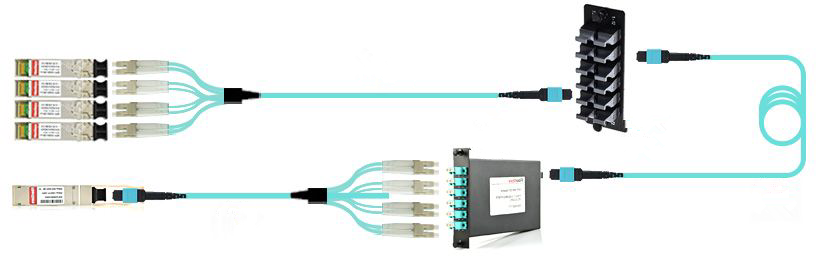
The first challenge comes to the cost. Migration to 40G isn’t a cost0saving project. The price of a 40G link is expensive than that of 4*10G links (as shown in the figure below). The 40G equipment that bridges applications and switching solutions for 40G is a main factor that causes the increase in budget. For instance, a QSFP transceiver, like QFX-QSFP-40G-SR4, a 40GBASE-SR4 QSFP+, is much more expensive than a 10GBASE-SR SFP+(eg. F5-UPG-SFP+-R), that is almost five times judging from the average market price.
- Drop in Optical Signal to Noise Ratio (OSNR)
The second one goes to the drop in OSNR. A unit of information, called a symbol, transmitted at 10Gbit/s takes 100 pico seconds (100ps), and the same symbol transmitted at 40Gbit/s takes 25ps. This means the receiver translating the light back into a symbol deals with only 25% of the light of a 10G symbol. It causes 6 dB OSNR to drop. The OSNR is a measure of the strength of the signal. So the drop of 6dB means the link length will be decreased by 75%.
- Increase in Chromatic Dispersion (CD)
When a signal travels through a fiber, CD causes the pulses constituting the signal to spread in time. If this spreading is not compensated, these pulses will overlap. It means the signal is unusable. Comparing to 10G, this effect is 16 times more obvious at 40G. This creates a serious roadblock for 40G system operating.
- Increase in Polarization Mode Dispersion (PMD)
PMD is the third problem which may be the most difficult to solve. This occurs due to infinitesimal imperfections in the circularity of the core of a fiber, which may be caused by the material itself, manufacturing process, or stress in the field created by bending or twisting. PMD is more capricious than predictable, and is very dependent on the qualities of the fiber. PMD can be influenced by factors including cable age or vintage, temperature of cable, cable design and cable manufacturer, etc.
Although migration from 10G to 40G encounters some difficulties mentioned above, several modulation schemes and approaches have been developed.
- About Cost Savings
40G migration requires the use of new equipment. As mentioned above, some optical equipment like transceivers from Google searching result are quite expensive. In order to save money, you can consider the third-party suppliers, such as Fiberstore, whose fiber optical products, including fiber optic transceivers and cables, are quality assured and fully compatible with major brands. Besides, these compatible products are sold at really low prices. For example, the price of QFX-QSFP-40G-SR4 listed in Fiberstore is just US$ 85.00 and F5-UPG-SFP+-R is US$ 16.00.
- About OSNR, CD, PMD Improvements
On one hand, problems related to OSNR, CD and PMD are directly caused by optics, the fiber quality and other optical equipment. So it’s highly recommended choose high quality equipment. On the other, such conditions also have relation to fiber optical technology. When 40G technology becomes maturer and maturer, simplified materials can be designed, and better solutions can be put forward.
With the increasing demands for higher-bandwidth applications, the trend of migration from 10G to 40G is inevitable. With the above methods migration challenges and solutions, you can upgrade to 40G network efficiently. Besides, to help customers achieve 40G smoothly, Fiberstore provides various 40G fiber optics products with high quality at lower prices. For more information about 40G solutions, please visit Fiberstore with no hesitation.
Posted by: fernxu123 at
03:00 AM
| No Comments
| Add Comment
Post contains 759 words, total size 6 kb.
April 07, 2016
When we try to compare the fiber optic cable with copper cable, we may be thrown into trouble most of the time. Actually, it is too difficult to be impartial because the pros and cons between them are so clear. Apparently, fiber optic cable outweighs copper cable in the aspect of speed or bandwidth. It is much faster than copper cable, carries much higher bandwidth, has less interference and is lighter, stronger and more durable as well. Considering this situation, today we will just take a closer look at the advantages of fiber optic cable over copper cable.
It’s known the copper cable transmits data by electrical impulses, while fiber optic cable, which is made up by hair-like glass fibers, sends signals by carrying light impulses transmitted by a LED or laser. The infrared light inside the fiber optic cable would bounce at blistering speeds until it reaches the other end of the fibers. After the optical receiver receives the signals, then the signals would be converted into data. Since the fiber optic cable transmits data by lasers, the speed of it must be much higher than copper cable. In this text, fiber optic cable advantages such as bandwidth will be talked about in details below.
Speed here refers to the amount of data that can be transmitted per unit of time. Needless to say, fiber optic cable has a great win over copper cable in speed. For example, traditional copper lines can usually carry roughly 3,000 phone calls at one time, while fiber optic cables used in a similar system could carry around 31,000 calls.
Unlike copper whose distance limitation is limited to 100m, fiber optic cable allows the distance to range 300m to 80km, depending on the style of cable, wavelength, and network. For instance, in Gigabit Ethernet (GbE) applications, multi-mode fiber (MMF), when used in combination with 1000BASE-SX SFPs (eg. MGBSX1) using 850nm wavelength, is bale to realize 550m link length. Or other, when single-mode fiber (SMF) works in corporation with 1000BASE-LX SFP (eg. EX-SFP-1GE-LX) using 1310nm wavelength, the possible link length is 10km.

Bandwidth is the key point that determines the speed of the cables. Because of the higher bandwidth, fiber optic cable can have the extremely high frequency ranges to carry data. This would be a thousand times the bandwidth of copper cable. If copper cable transmits data at high frequencies, its signal strength will diminish. Without any exaggeration, the fiber optic cable can go more than one hundred times further, while the copper cable could only hold a candle.
Fiber optic cable permits extremely reliable data transmission. Because the core is made of glass, which is an insulator, no electric current can flow through a fiber optic cable. Besides, fiber immune to many environmental factors that have effects on copper cable, immune to electromagnetic interference and radio-frequency interference (EMI/RFI), crosstalk, impedance problems, and more. You can run fiber next to industrial equipment without worry. In addition, fiber is also less susceptible to temperature fluctuations than copper is, and it can be submerged in water. More importantly, fiber optic cable can carry more information with greater fidelity than copper wire can. That’s why telephone and CATV companies are converting to fiber.
Fiber is light in weight, thin, and more durable than copper cable. Additionally, fiber optic cable has pulling specifications that are up to 10 times greater than copper cable’s. Its small size (just as the below figure shows) makes it easier to handle, and it takes up much less space in cabling ducts. Although fiber is still more difficult to terminate than copper, advancements in connectors are making termination easier. In addition, fiber is actually easier to test than copper cable.

Fiber optic systems are already being used in the backbone applications of most major companies because of their reliability and upgradability. All up, it is fairly safe to assume that, just as digital telephony has done in the past, so fiber optic technology will move ahead with big steps leaving the traditional copper wire behind.
Fiberstore is a company offering fiber connectivity network solutions for carriers, ISPs, content providers and networks, and also the global market innovator and application technology pioneer in the field of optical network devices and interconnection, especially on fiber optic cables and fiber optic transceivers which are fully compatible with major brands, such as Cisco Linksys MGBSX1 and Juniper Networks EX-SFP-1GE-LX mentioned above. If you have any further questions about fiber optic networks, or you want to purchase fiber optic items, please visit Fiberstore.
Posted by: fernxu123 at
06:26 AM
| No Comments
| Add Comment
Post contains 772 words, total size 6 kb.
April 05, 2016
Owing to the rapid progresses made in fiber optical technology, more and more networking infrastructure installations and upgrades choose fiber optic links for high-data-rate transmission. There is no question that compared with copper solutions, fiber optics provides greater bandwidth, more reliable data transmission, and immunity to electromagnetic interference and radio-frequency interference (EMI/RFI), crosstalk, impedance problems, and more. For constituting such fiber optic links, fiber optical modules, one of the fast-growing transmission components, are instrumental, and work well in these applications where high-bandwidth and long-distance transmission are needed.
Along with the fiber optical technology advances, fiber optical modules have been constantly designed and re-innovated, so as to better facilitate electrical-optical-electrical signal conversion. They are classified into several categories according to different standards regarding package, transmission mode, data rate and power supply. This text will talk about every classification standard in details.
MSAs (Multi-Source Agreements) are agreements between multiple manufacturers, system integrators, and suppliers, specifying parameters for system components and their guideline values, such as the electrical and optical interfaces, mechanical dimensions and electro-magnetic values. The equipment vendors follow these MSA defined values for designing their systems to ensure interoperability between interface modules. The form-factor or the MSA-type is needed so that the transceiver can mechanically and electrically fit into a given switch, router, etc. Transceiver MSAs define mechanical form factors including electric interface as well as power consumption and cable connector types. There are various MSA types: SFP (eg. E1MG-TX), SFP+, QSFP and so on.

When talking about this standard, single-mode optical modules and multi-mode optical modules come to the central point.
- Single-mode Optical Modules
Single-mode optical modules, or single-mode transceivers, just as their name show, are designed to work over single-mode fibers (SMFs). Compared with multi-mode fiber (MMF), SMF fiber core is smaller and the wavelength of the laser is narrower, meaning that while transmitting optical signals, SMF is able to deliver higher bandwidth at the much longer distances, like 2km, 10km, 40km, 60km, 80km and 120km transmission. Commonly-seen single-mode transceiver types include 10GBASE-LR, 1000BASE-LR, 1000BASE-BX, etc..
- Multi-mode Optical Modules
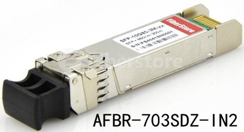
Multi-mode optical modules, or multi-mode transceivers, operate over MMF which uses a much bigger core and usually uses a longer wavelength of light. Thus, the optics used in MMF has a higher capability to gather light from the laser, for short distance transmission, with distance reach ranging from 100m to 500m. 10GBASE-SR is one of the most widely-used multi-mode transceiver types, such as AFBR-703SDZ-IN2. This Avago Intel compatible 10GBASE-SR SFP+ transceiver listed in Fiberstore works over MMF with 850nm laser light for 300m distance reach.
- The connection between two network devices is realized with the help of protocols. It is imperative to know which protocol and data rate the switch or router supports. There are various protocols such as Ethernet, Fiber Channel (FC), InfiniBand, SONET/SDH, CPRI and so on. Each of these protocols supports their own data rates. For example Gigabit Ethernet (GbE) can range from 1Gb/s to 100Gb/s, while FC ranges from 1GFC (1.0625Gb/s) to 16GFC (14.025Gb/s).
- As for power supply, there are built-in switching power transceiver and eternal power supply transceiver. The built-in switching power transceiver is designed for the carrier grade power. It supports equipment power protection, filters, and a wide power supply voltage regulator, reducing the external point of failure arising from the mechanical contact. By contrast,the external power supply transceiver is made for multi-use civilian equipment, and it is compact and cheap.
- Of course, the classification standards of fiber optical modules are not limited to those three points mentioned above. Other standards are also workable, such as the network management standard. It’s known that there are managed optical modules and unmanaged optical modules. The former type allows additional network monitoring with fault detection, free from configuration function. By contrast, the latter, without monitoring function, allows automatic communication of the devices that are connected to unmanaged optical modules.
When your networking projects call for fiber optical modules for fiber optic links, these classification standards will work, since they help you to choose the right fiber optical modules for applications to ensure the reliable data transmission. Fiberstore offers an ocean of fiber optical modules which are fully compatible with major brands, including the Brocade E1MGTX, and Avago Intel AFBR-703SDZ-IN2 mentioned above. For more information about fiber optical modules, you can visit Fiberstore.
Posted by: fernxu123 at
03:25 AM
| No Comments
| Add Comment
Post contains 738 words, total size 7 kb.
March 31, 2016
New sophisticated networking services, coupled with the increase of Internet users push the Internet traffic to an even higher point, driving the need for increased bandwidth consequently. One Ethernet technology—10 Gigabit Ethernet (GbE) is adequate for such bandwidth demand, and has become widely available due to the competitive price and performance, as well as its simplified cabling structure.
Several cable and interconnect solutions are available for 10GbE, the choice of which depends on the maximum interconnect distance, power budget and heat consumption, signal latency, network reliability, component adaptability to future requirements, cost. Here cost includes more than what we call the equipment interface and cable cost, but more often the labor cost. Thus, choosing a 10GbE interconnect solution requires careful evaluation of each option against the specific applications. This text aims to introduce two main 10GbE interconnect solutions: fiber optics and copper.
Fiber optic cables include single-mode fiber (SMF) and multi-mode fiber (MMF). MMF is larger in diameter than that of single-mode, thus portions of the light beam follow different paths as they bounce back and forth between the walls of the fiber, leading to the possible distorted signal when reach the other end of the cable. The amount of distortion increases with the length of the cable. The light beam follows a single path through thinner single-mode cable, so the amount of distortion is much lower.

The typical 10GBASE port type that uses MMF is 10GBASE-SR which uses 850nm lasers. When used with OM3 MMF, 10GBASE-SR can support 300m-connection distances, and when with OM4 MMF, 400m link length is possible through 10GBASE-SR SFP+ transceiver.
10GBASE-LR (eg. E10GSFPLR), 10GBASE-ER and 10GBASE-ZR are all specified to work via SMF. SMF can carry signals up to 80km, so it is more often used in wide-area networks. But since SMF requires a more expensive laser light source than MMF does, SMF is replaced by MMF when the required connection distance is not so long.
10GBASE-CX4, SFP+ Direct Attach (DAC) and 10GBASE-T are all specified to operate through copper medium.
- 10GBASE-CX4
Being the first 10GbE copper solution standardized by the IEEE as 802.3ak in 2002, 10GBase-CX4 uses four cables, each carrying 2.5gigabits of data. It is specified to work up to a distance of 15m. Although 10GBase-CX4 provides an extremely cost-effective method to connect equipment within that 15m-distance, its bulky weight and big size of the CX4 connector prohibited higher switch densities required for large scale deployment. Besides, large diameter cables are purchased in fixed lengths, causing problems in managing cable slack. What’s more, the space isn’t sufficient enough to handle these large cables.
- SFP+ DAC
SFP+ Direct Attach Cable (DAC), or called 10GSFP+Cu, is a copper 10GBASE twin-axial cable, connected directly into an SFP+ housing. It comes in either an active or passive twin-axial cable assembly. This solution provides a low-cost and low energy-consuming interconnect with a flexible cabling length, typically 1 to 7m (passive versions) or up to 15m (active versions) in length. Below is the SFP+ to SFP+ passive copper cable assembly with 1m length, 487655-B21, a HP compatible 10GbE cabling product.

- 10GBASE-T
10GBASE-T, known as IEEE 802.3an-2006, utilizes twisted pair cables and RJ-45 connectors over distances up to 100m. Cat 6 and Cat 6a are recommended, with the former reaching the full length at 100m, and the latter at 55m. In a word, 10GBASE-T permits operations over 4-connector structured 4-pair twisted-pair copper cabling for all supported distances within 100m. Besides, 10GBASE-T cabling solution is backward-compatible with 1000BASE-T switch infrastructures, keeping costs down while offering an easy migration path from 1GbE to 10GbE.
In summary, two main media options are available for 10GbE interconnect: copper and fiber optics, including 10GBASE-CX4, SFP+ DAC, 10GBASE-T, 10GBASE-SR, 10GBASE-LR, 10GBASE-ER, 10GBASE-ZR, and so on. Fiberstore offers all these 10GBASE SFP+ modules and cables for your 10GbE deployment, which are quality-assured and cost-effective, like E10GSFPLR and 487655-B21 mentioned above. For more information about 10GbE interconnect solutions, you can visit Fiberstore.
Posted by: fernxu123 at
03:24 AM
| No Comments
| Add Comment
Post contains 664 words, total size 6 kb.
March 28, 2016
A continuous stream of manufacturing process improvements and product innovations has given fiber optical system several advantages, like longer distance reach, larger data-carrying capacity, greater bandwidth and lower power consumption. Among these fiber optical product innovations, hot-pluggable transceiver modules should come to the central point with their unique designs. They have been constantly designed, and finally been reinvented as hot-pluggable modules along with the optical technological advances. These small, hot-pluggable serve as the key components in accommodating the demands of higher port density and more networking flexibility.
Transceiver modules come into various types: SFP (small form-factor pluggable), SFP+ (small form-factor pluggable plus), QSFP+ (quad small form-factor pluggable plus), etc. This article mainly introduces SFP transceiver modules which are widely applied in Gigabit Ethernet (GbE) applications, with the focus on several 1000BASE-X interface types, including 1000BASE-SX, 1000BASE-LX, 1000BASE-EX, and 1000BASE-BX10-D/U.
1000BASE-X SFP modules provide a wide range of form factor options for enterprise and service provider needs. They are designed with the following features and benefits:
- Hot swappable to maximize uptime and simplify serviceability;
- Flexibility of media and interface choice on a port-by-port basis, so you can "pay as you populateâ€;
- Sophisticated design for enhanced reliability;
- Supports digital optical monitoring (DOM) function;
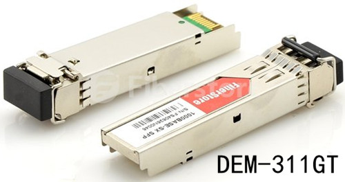
1000BASE-SX SFP, compatible with the IEEE 802.3z 1000BASE-SX standard, operates on legacy 50μm multi-mode fiber (MMF) links up to 550m and on 62.5μm Fiber Distributed Data Interface (FDDI)-grade MMFs up to 220m. Take DEM-311GT for example, Fiberstore compatible D-Link 1000BASE-SX SFP is able to realize 550m link length through OM2 MMF with duplex LC.
1000BASE-LX SFP, compatible with the IEEE 802.3z 1000BASE-LX standard, is specified to support link length of up to 10km on standard single-mode fiber (SMF), to 550m on MMFs. When used over legacy MMF, the transmitter should be coupled through a mode conditioning patch cable. The laser is launched at a precise offset from the center of the fiber which causes it to spread across the diameter of the fiber core, reducing the effect known as differential mode delay which occurs when the laser couples onto only a small number of available modes in MMF.
1000BASE-EX SFP1000BASE-EX, sometimes referred to as LH, is a non-standard but industry accepted standard which works on standard SMF with fiber link spans up to 40km in length. For back-to-back connectivity, a 5-dB inline optical attenuator should be inserted between the fiber optic cable and the receiving port on the SFP at each end of the link. 1000BASE-EX SFPs (eg. GLC-EX-SMD) run on 1310nm wavelength lasers, and achieves 40km link length.
1000BASE-BX10-D/U SFPThe 1000BASE-BX-D and 1000BASE-BX-U SFPs, compatible with the IEEE 802.3ah 1000BASE-BX10-D and 1000BASE-BX10-U standards, operate on a single strand of standard SMF (figure shown below). A 1000BASE-BX10-D device is always connected to a 1000BASE-BX10-U device by a single strand of standard SMF with an operating transmission distance up to 10km.

The communication over a single strand of fiber is accomplished by separating the transmission wavelength of the two devices (figure shown above): 1000BASE-BX10-D transmits a 1490nm channel and receives a 1310nm signal, whereas 1000BASE-BX10-U transmits at a 1310-nm wavelength and receives a 1490-nm signal. In this figure, the wavelength-division multiplexing (WDM) splitter is integrated into the SFP to split the 1310nm and 1490nm light paths.
These 1000BASE-X SFP modules provide physical layer connectivity for optical-port modular switch IO blades and optical-port stackable switches, reliable, and cost-effective choices to accommodate varied and evolving network demands. As a professional fiber optic product manufacturer and supplier, Fiberstore supplies all the above-mentioned several 1000BASE-X SFP modules which are all test- and quality-assured. You can visit Fiberstore for more information about 1000BASE-X SFP modules.
Posted by: fernxu123 at
03:06 AM
| No Comments
| Add Comment
Post contains 617 words, total size 6 kb.
March 24, 2016
Thanks to the advances made in fiber optical technologies, fiber solutions have been deployed in ever-increasing applications where high-speed and high-performance data transmission is needed. They outweigh the copper solutions in such aspects as higher bandwidth, longer distances and Electromagnetic interference (EMI) immunity. Transceivers, one of the key components required in such fiber connections for high networking performance, have experienced the never-ceasing industrial designs, from lower port density to higher, from the standard modules to the final hot-pluggable ones, to meet the ever more flexible networking infrastructure.
There is a broad selection of hot-pluggable transceiver modules available for fiber networking use, and you may feel a little confused about how to select the correct transceivers for your networking transmission. In this article, I will illustrate different aspects of transceivers that need to be known before choosing a transceiver.
Before giving guidance to transceiver selection, it’s necessary to know the basics of transceiver. Transceiver is a combination of a transmitter and a receiver in a single package, while they function independently for bidirectional communication. Typically, a fiber optic transceiver converts the incoming optical signal to electrical and the outgoing electrical signal to optical. More specifically, the transmitter takes an electrical input and converts it to an optical output from a laser diode or LED. The light from the transmitter is coupled into the fiber with a connector and is transmitted through the fiber optic cable plant. The light from the end of the fiber is coupled to a receiver where a detector converts the light into an electrical signal which is then conditioned properly for use by the receiving equipment.
Here go the several aspects of transceivers that are helpful in your purchasing.
Multi-source agreements (MSAs) between different equipment vendors specify guidelines for electrical and optical interfaces, mechanical dimensions and electro-magnetic specification of a transceiver. The equipment vendors follow these MSA defined values for designing their systems to ensure interoperability between interface modules. The form-factor or the MSA-type is needed so that the transceiver can mechanically and electrically fit into a given switch, router, etc. Transceiver MSAs define mechanical form factors including electric interface as well as power consumption and cable connector types. There are various MSA types: SFP (eg. MGBSX1), SFP+, XFP, CFP, CFP2, CFP4, QSFP and so on.

Transceivers can work over single-mode fiber (SMF), multi-mode fiber (MMF), and copper. In different Ethernet applications, media can achieve different link lengths when combined with transceivers. Take Gigabit Ethernet (GbE) applications for example, single-mode transceivers can have a transmission distance of 5km to 120km, while multi-mode transceivers are defined to have the maximum reach of 55om, with copper solution establishing even fewer link length at 25m. Take MGBLX1 for example, this Cisco compatible 1000BASE-LX SFP works through SMF for 10km reach.
The transceiver power budget is the difference between transmitter launch power and receiver sensitivity and has to be 2-3dB larger (Margin) than the measured link loss. If the link loss cannot be measured, it has to be calculated. Therefore transmission distance [km], the number of ODFs, patches and passive optical components (Muxes) have to be known. Common values for power budget are <10, 14, 20, 24, 28, >30dB.
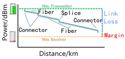
If you’re seeking high-speed data carrier, transceivers can help accomplish goals. By transmitting data at 10Gbit/s, 40Gbit/s, 100Gbit/s or 12940Gbit/s, they can ensure that data arrives quickly. Transceiver modules that are capable of handling fast speeds can help with downloads and high and low bandwidth video transmission.
Transceivers are instrumental in ensuring that the data is transmitted securely, expeditiously, and accurately across the media. Choosing the right type of transceiver for your network is not always easy, but knowing above discussed parameters beforehand helps you narrow it down to a few transceivers. Fiberstore offers a sea of transceiver modules which are fully compatible with major brands, like the above mentioned MGBSX1 and MGBLX1, the Cisco compatible transceiver modules. For more information about transceiver modules, you can visit Fiberstore.
Posted by: fernxu123 at
03:35 AM
| No Comments
| Add Comment
Post contains 671 words, total size 6 kb.
March 22, 2016
The rapid expansion of fiber optic networks, including data services measured by data volume or bandwidth, shows that fiber optic transmission technology is and will continue to be a significant part of future networking systems. Network designers are becoming increasingly comfortable with fiber solutions, since the use of which allows for more flexible network architecture and other advantages, such as EMI (Electromagnetic Interference) resilience and data security. Fiber optic transceivers play an really important role in these fiber connections. And while designing fiber optic transceivers, three aspects need to be considered: environmental situation, electrical condition and optical performance.
The fiber optic transceiver is a self-contained component that transmits and receives signals. Usually, it is inserted in devices such as routers or network interface cards which provide one or more transceiver module slot. The transmitter takes an electrical input and converts it to an optical output from a laser diode or LED. The light from the transmitter is coupled into the fiber with a connector and is transmitted through the fiber optic cable plant. Then the light from the end of the fiber is coupled to a receiver where a detector converts the light into an electrical signal which is then conditioned properly for use by the receiving equipment. There are a full range of optical transceivers available in telecommunication market, like SFP transceiver, SFP+ transceiver (eg. SFP-10G-SR shown below), 40G QSFP+, 100G CFP, etc.
It’s true that fiber links can handle higher data rates over longer distances than copper solutions, which drive the even wider use of fiber optic transceivers. While designing fiber optic transceivers, the following aspects should be taken into consideration.
- Environmental Situation
One challenge comes to the outside weather—especially severe weather at elevated or exposed heights. The components must operate over extreme environmental conditions, over a wider temperature range. The second environmental issue related to the fiber optic transceiver design is the host board environment which contains the system power dissipation and thermal dissipation characteristics.
A major advantage of the fiber optic transceiver is the relatively low electrical power requirements. However, this low power does not exactly mean that the thermal design can be ignored when assembling a host configuration. Sufficient ventilation or airflow should be included to help dissipate thermal energy that is drawn off the module. Part of this requirement is addressed by the standardized SFP cage which is mounted on the host board and also serves as a conduit for thermal energy. Case temperature reported by the Digital Monitor Interface (DMI), when the host operates at its maximum design temperature, is the ultimate test of the effectiveness of the overall system thermal design.
- Electrical Condition
Essentially, the fiber transceiver is an electrical device. In order to maintain error free performance for the data passing through the module, the power supply to the module must be stable and noise-free. What’s more, the power supply driving the transceiver must be appropriately filtered. The typical filters have been specified in the Multisource Agreements (MSAs) which have guided the original designs for these transceivers. One such design in the SFF-8431 specification is shown below.

- Optical Performance
Optical performance is measured as Bit Error Rate, or BER. The problem facing designing optical transceiver lie in the case that the optical parameters for the transmitter and receiver have to be controlled, so that any possible degradation of the optical signal while traveling along the fibers will not cause poor BER performance. The primary parameter of relevance is the BER of the complete link. That is, the start of the link is the source of the electrical signals which drive the transmitter, and at the end, the electrical signal is received and interpreted by the circuitry in the host by the receiver. For those communication links which use optical transceivers, the primary goal is to guarantee BER performance at different link distances, and to ensure broad interoperability with third party transceivers from different vendors.
Fiber technology is becoming maturer, leading to the wider use of fiber optic transceivers. With the three aspects mentioned above in mind, designing fiber optic transceivers should be easier. Fiberstore supplies many transceivers which are fully compatible with major brands, including HP compatible transceivers (eg. J4858C). For more information about fiber optic transceivers, you can visit Fiberstore.
Posted by: fernxu123 at
02:45 AM
| No Comments
| Add Comment
Post contains 725 words, total size 6 kb.
March 18, 2016
The commitment to fiber optic technology has spanned more than 30 years, and nowadays a high level of glass purity, fiber optic cable, has been achieved owing to the continuous research and development. This purity, combined with improved system electronics, enables to transmit digitized light signals over hundreds of kilometers with high performance, offering many advantages in fiber optic systems. This text provides an overview of the construction, categories, and working principles of this fiber optic cable.
Fiber optic cable generally consists of fiver elements : the optic core, optic cladding, a buffer material, a strength material and the outer jacket. Here, much more detailed information is attributive to the optic core and optic cladding which are both made from doped silica (glass).
The Optic Core and Cladding DetailsThe optic core is the light-carrying element at the center of the cable, and the optic cladding surrounds the optic core. Their combination makes the principle of total internal reflection possible. Besides, a protective acrylate coating then surrounds the cladding. In most cases, the protective coating is a dual layer composition: a soft inner layer that cushions the fiber and allows the coating to be stripped from the glass mechanically, and a harder outer layer that protects the fiber during handling, particularly the cabling, installation, and termination processes. This coating protects the glass from dust and scratches that can affect fiber strength.
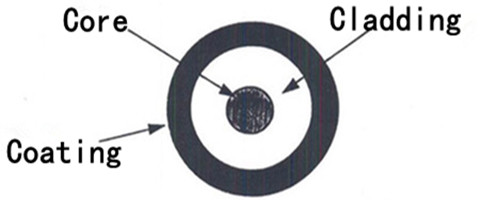
There are two general categories of fiber optic cable: single-mode fiber (SMF) and multi-mode fiber (MMF).
MMF was the first type of fiber to be commercialized. It has a core of 50 to 62.5 µm in diameter much larger than SMF, allowing hundreds of modes of light to propagate through the fiber simultaneously. Additionally, the larger core diameter of MMF facilitates the use of lower-cost optical transmitters (such as light emitting diodes or vertical cavity surface emitting lasers) and connectors, more suitable for relatively shorter-reach application. Take 1 Gigabit Ethernet (GbE) applications for example, MMF is deployed to establish 550m link length with 1000BASE-SX SFPs (eg. Cisco Meraki MA-SFP-1GB-SX).
SMF, in contrast, has a much smaller core, approximately 8 to 10 µm in diameter, which allows only one mode of light at a time to propagate through the core. It’s designed to maintain spatial and spectral integrity of each optical signal over longer distances, permitting more information to be transmitted. Similarly, as for 1GbE applications, SMF is able to realize 70km reach with 1000BASE-ZX SFPs, like GLC-ZX-SM, a product compatible with Cisco listed in Fiberstore.

The operation of a fiber optic cable is based on the principle of total internal reflection. Light reflects (bounces back) or refracts (alters its direction while penetrating a different medium), depending on the angle at which it strikes a surface.
This principle comes at the center of how fiber optic cable works. Controlling the angle at which the lightwaves are transmitted makes it possible to control how efficiently they reach their destination. Lightwaves are guided through the core of the fiber optic cable in much the same way that radio frequency (RF) signals are guided through coaxial cable. The lightwaves are guided to the other end of the fiber being reflected within the core. The composition of the cladding glass related to the core glass determines the fiber’s ability to reflect light. That reflection is usually caused by creating a higher refractive index in the core of the glass instead of in the surrounding cladding glass, creating a waveguide. The refractive index of the core is increased by slightly modifying the composition of the core glass, generally by adding small amounts of a dopant. Alternatively, the waveguide can be created by reducing the refractive index of the cladding using different dopants.
In fiber optic cables, the light can carry more information over longer distances than the amount carried in a copper or coaxial medium or radio frequencies through a wireless medium. With few transmission losses, low interference, and high bandwidth, fiber optic cables are the ideal transmission medium. Fiberstore offers various kinds of fiber optic cables, including SMF and MMF types, simplex and duplex fiber optic cables, indoor distribution cables and outdoor loose tube cables, etc. For more information about fiber optic cables, you can visit Fiberstore.
Posted by: fernxu123 at
03:13 AM
| No Comments
| Add Comment
Post contains 726 words, total size 6 kb.
March 16, 2016
Today’s data centers growth is placing increasing demands on the networking infrastructure. For some enterprises, existing 1GbE connections can’t support the growing business requirements well very, not to say 100Mbps connections. In order to accommodate these demands, it’s imperative to upgrade the data center network architecture to 40 or 100 Gigabit Ethernet (GbE) connections. This 40/100GbE network design helps to support not only the current growth, but also the increasing demands in the future.
The Institute of Electrical and Electronics Engineers (IEEE) 802.3 working group is concerned with the maintenance and extension of the Ethernet data communications standard. And 802.3ba is the designation given to the higher speed Ethernet task force to modify the 802.3 standard to support higher speeds than 10Gbit/s, that is 40/100G in 2010. This 802.3ba 40/100G standard encompasses a number of different Ethernet physical layer (PHY) specifications which are supported by means of pluggable modules, like Quad Small-Form-Factor Pluggable (QSFP) and C Form-Factor Pluggable (CFP). As for transmission medium, the transport speeds at 40/100Gbit/s use two methods: parallel optics and copper cables, with the fiber optics solutions allowing more flexibility and greater distance reach.
In most cases, 40GbE connections use a QSFP+ transceiver terminated to receive the multi-fiber push-on/multiplex pass-through (MPO/MPT) trunk. That is, the short-range QSFP+ transceivers (eg. QFX-QSFP-40G-SR4) use multi-mode MPO trunks to establish 40G links. During this link establishment, polarity becomes a consideration when implementing 40GbE switch-to-switch interconnects over multi-strand multi-mode fiber (MMF). Method B polarity is recommended for the functional link.
QSFP+ transceivers are also able to run on single-mode fiber (SMF) for long reach. These links are Little Connector (LC) terminated and can run up to 40km, mainly used for 40GbE interbuilding connections. Take QSFP-40G-ER4 for example, this 40GBASE-ER4 transceiver supports link lengths up to 40km over SMF with duplex LC connectors.
The QSFP+ transceiver can also be used for 40GbE to 4x10GbE partitioned applications, that is QSFP+ to 4SFP+ fan-out cabling assemblies. One end of the connection is terminated using a MPO/MPT configuration with four individual pairs terminated with LC connectors at the other end. The image below just shows the QSFP+ to 4SFP+ Active Optic Cable (AOC) assembly.

100GbE connections use a CFP transceiver. Two CFP options are dominant in the industry: CFP2 and CFP4. The primary differences between the two are physical density and transmit/receive lane configurations. More specifically, CFP2 supports 100GBASE-SR10, 100BASE-LR4, and 100GBASE-ER4 optical interfaces, while CFP4 doubles the port density on the line card and supports 100GBASE-SR4, 100GBASE-LR4, and 100GBASE-ER4 optical interfaces.

The 40/100GbE network infrastructure provides the following benefits:
- Reduced data center complexity: As virtualization increases, the use of fewer physical servers and switches has been made possible by 40/100GbE network infrastructure.
- Reduced total cost: Since 40/100GbE network system simplifies the local area network (LAN) and cable infrastructures, the potential cost reduction in virtualization environment is also accessible. Besides, the 40/100GbE network infrastructure requires fewer data center space, power, and cooling resources.
- Increased Productivity: Faster connections and reduced network latency provide network designers with faster workload completion times and improved productivity.
- Upgrading network architecture to support speeds greater than 10GbE, that is 40/100GbE, is essential in optimizing data center infrastructure, giving a hand in moving quickly in respond to business needs. At the same time, the services and value brought by information technology itself can also be enhanced.
The high-performance 40/100GbE network architecture simplifies the cabling infrastructure and reduces per-server total cost of ownership, capable of allowing high speeds at 40/100Gbit/s. Fiberstore offers a large selection of 40/100G optical modules, as well as 40/100G fiber optic-based cables and copper cables. For more information about 40/100GbE solutions, you can visit Fiberstore.
Originally published at www.fiber-optic-cable-sale.com/overview-of-40100gbe-terminations.html
Posted by: fernxu123 at
09:14 AM
| No Comments
| Add Comment
Post contains 628 words, total size 6 kb.
30 queries taking 0.0731 seconds, 114 records returned.
Powered by Minx 1.1.6c-pink.

