February 10, 2017
For many IT manager or data center professionals, one of the most difficult task is to keep cables in proper order. Image that you walk into a sever room to troubleshoot cables because of the bad cable management, you see the cable here, cable there, cable everywhere. Can you walking through this without crying?
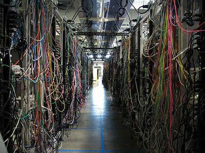
Now that you have looked at the horrible cable management, it is time for you to do something to avoid joining the terrible cable management hall.
From the above image, we can see that there are bunches of cables in one sever room, which includes power cables, network cables, and in some cases, keyboard or mouse cables. In this situation, proper rack cable management is absolutely essential. Without it, you will need to trace out every cable in the rack anytime, this, of course, can be very time consuming and difficult.
Fortunately, there are many excellent products available on the market, such as cable manager, wire duct, patch panel, cable ties and so on, which can help make cable management in rack environments much faster, easier and more effective. Whether you handle running cables for a massive corporate data center or for a small business, learning more about cable management can be very helpful. This article will have a brief introduction to the vertical and horizontal cable managers.
Vertical & Horizontal Cable Manager
Good cable management is essential. When installing cables in a sever rack, you will undoubtedly have to run them both vertically and horizontally. The best solution for this cabling is to run all the cables horizontally from the sever directly to the vertical cable management rack. In this case, you would need the cable managers to hold the cables smugly and safely. This vertical and horizontal cable manager provides plenty of room for all the cables.
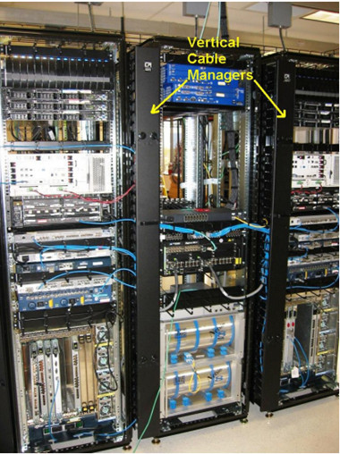
Vertical cable manager just as seen in the below image, utilizes the additional space to manage the slack from patch cords, and make sure that they can easily route the largest cable diameter in your plan. For static environments, you can consider installing another vertical cable manager behind the racks, which does not block access to components in the space between the racks. Vertical racks can be also installed under a desk or against a wall and accommodate networking equipment up to 4 RU.
Horizontal cable managers allow neat and proper routing of the patch cables from equipment in racks and protect cables from damage. If you are using flat-faced patch panels or network switches that cable from above or below, horizontal cable manager will complete the support pathway for patch cords between the cabling section and the exact connection point (port) on the patch panel or switch. Alternately, horizontal management can be used to create rack-to-rack pathways for patch cords. The following image shows the 2u horizontal cable manager panel.
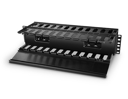
Select a style of horizontal cable management that complements the cabling section (vertical manager). Generally, it is good practice to plan 1U of horizontal cable management for every 2U of connectivity. Cable fill should equal at minimum, half of the ports supported by the cable manager. This method assumes that patch cords enter from both sides of the rack. Capacity should equal port density when cables enter from one side of the rack only.
In some case, vertical cable manager and horizontal cable manager are often used together. The vertical cable manager guides cables to the floor and horizontal cable management draws away from equipment.
FS.COM Cable Manager
FS.COM cable management provides an engineered solution for managing high-density cabling applications, delivering increased performance to match the demands of data center applications. Use FS.COM Vertical and Horizontal Cable Managers on the sides of racks to manage premise cables, patch cords and jumper cords.
Features include:
- Four styles: Finger duct, D-rings, Brushed, Telephone Line
- Structure: Single-sided, Double-sided
- Available in a variety of heights, depths and widths (rack up to 45 U)
- Material: plastic, metal, semimetal
- Vertical manager door opens to right or left with single knob; horizontal manager has snap-on cover
- Rigid vertical manager trough minimizes movement when installed on the end of a row or racks; full rectangular base supports heavy cable bundles
- Vertical cable managers feature panels that support various optional cable management accessories to divide the interior space and manage cable slack
- The panel on dual-sided vertical managers are movable and allow for flexibility in the volume of cable management space
- Wide variety of accessories include cable ties, cable management rings, cable lacing bars, J-hook and wire loom.
Conclusion
If you have picked the right rack cable manager (whether the vertical cable manager or the horizontal cable manager), the next important thing you should do is make sure you make a good preparation before deploying. Plan out every detail of the installation will help to ensure the cable management activities perform as quickly and easily as possible.
Posted by: fernxu123 at
08:47 AM
| No Comments
| Add Comment
Post contains 819 words, total size 7 kb.
January 04, 2017
Different systems have a functional unit that serves as a central location for monitoring and connecting circuits. In the case of optical cabling, patch panels represent the functional unit, which are used to connect and disconnect equipment. Without them, the transmission of data is rendered ineffective. Patch panels allow one to terminate long and troublesome cables so that a signal is connected directly through a patch code to its destination. Patch panels, as a crucial (and often overlooked) element of any interconnected network will be introduced in this article.
Why Do We Need Patch Panels?
There is no denying that patch panels are the crucial elements in cabling systems no matter how big or small. It is said that patch panels are basically pictured as the "traffic light†for a cabling network, and they allow you to terminate cable elements and the signal to be connected to the final destination. In addition, patch panels are found in the telecommunications section of a building, enabling the ease of managing telecommunications networks.
Patch panels are so critical to a system that if anything goes wrong with them, the entire system may fail. That means that they are very important to your networking system! Patch panels also play a big role in the administration of the telecommunications network. Some believe that they are the absolute only way to successfully transfer lines from one office to the next office.
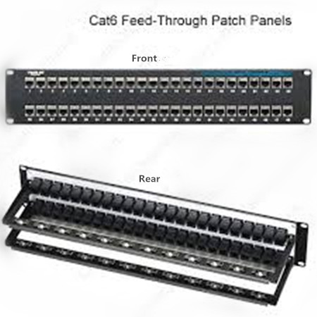
Figure 1 shows the front and rear of a cat6 patch panel
Since they allow such easy management of cables, it makes sense to choose patch panels carefully. There are copper patch panels and fiber patch panels available on the market. If you use both, it is best to separate the cabling made out of fiber from cabling made from copper. But what if you want to choose between copper and fiber patch panels? Which kind is best?
Copper or Fiber Patch Panels
First, you should know that patch panels are used in fiber cabling networks as well as copper cabling networks. So is there a difference between these two types of cables as far as performance is concerned? Well, most professionals don’t see any differences. But others believe that the fiber patch panels are better, even though they are more expensive than their copper counterpart. In fact, they can be up to 40 percent higher in cost.
When it comes to copper patch panels, each pair of wires has a port. Fiber patch panels require two ports, but no hardwiring is needed. Fiber patch panels are a lot easier to install because of this. The fiber is fed through a coupler.
In addition, most professionals are in agreement that fiber is a lot faster than copper patch panels. Both types of patch panels must perform according to the same TIA/EIA standards that are needed to produce speed and signal performance for the rest of the cabling network.
FS.COM Copper Patch Panels
FS.COM Cat5e and Cat6 copper patch panels are the cost-effective solutions for your applications. Take our cat5e patch panels as an example, they are compliant with TIA/EIA 568 industry specifications. These patch panels can maximize your network performance and keep up with the growing changes in your network. FS.COM Cat5e patch panels are available in 6-port and 8-port module groupings, in 8, 12, 24, and 48-port sizes. The high density panel design can be mounted to standard racks or cabinets, accommodate top, bottom or side cable entry, and also save valuable rack space.
Posted by: fernxu123 at
07:25 AM
| No Comments
| Add Comment
Post contains 584 words, total size 4 kb.
December 27, 2016
Nowadays more and more fiber-based networks have been built in the backbone and risers environment. Both multimode and single-mode fibers are available for the applications. But different fiber types have briefly different limitations for speed and maximum distance. These characteristics they possess and the way cause the fiber to operate determine the application to which a given fiber is most appropriate. Today’s article will offer you some information about the classification of fiber optic cables and the difference in speed and distances.
Difference Between OM Multimode Fibers
Multimode fibers, according to the specification and briefly by their bandwidth performance are commonly classified into OM1, OM2, OM3 and OM4. Each multimode type has different transmission data rates, link length and bandwidth for specific protocols, applications and transceiver types. Table 1 outlines the international standards organization classification for multimode fiber which describe the strength for speed and distance.
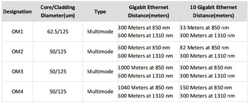
From the above table, we can see that OM1 is the 62.5-micron fiber, while OM2/OM3/OM4 are the 50-micron multimode fibers. OM1 multimode fiber was used to be the most common multimode fibers in the 80’s and 90’s. However, it is generated accepted that OM1 will soon be obsolete for the lowest data carrying capacity and shortest distance limitations as compared with other multimode fibers. As for the 50-micron multimode fibers, they are the most commonly used fiber types today, especially the OM3 and OM4 cables. Why do the multimode fibers with a smaller diameter have better performance than the large one? Please read on.
In terms of the performance in 50-micron and 62.5-micron multimode fibers, the difference lies in the fibers' bandwidth, or the signal-carrying capacity. Bandwidth is actually specified as a bandwidth-distance product with units of MHz-km that depends on the data rate. As the data rate goes up (MHz), the distance that rate can be transmitted (km) goes down. Thus, a higher fiber bandwidth can enable you to transmit at higher data rates or for longer distances. For example, 50-micron multimode fiber offers nearly three times more bandwidth (500 MHz-km) than FDDI-grade 62.5-micron fiber (160 MHz-km) at 850 nm.
While fiber bandwidth is a critical factor in determining link length and data rate, transmitter and receiver characteristics also matters. For 850-nm Gigabit Ethernet, these bandwidth values support link lengths of 220 meters over 62.5-micron fiber and 550 meters over 50-micron fiber. For example, Cisco GLC-SX-MM operating at 850-nm can support a link distance of 550 m over 50-micron fiber (OM2). Today, the 850-nm operating window is increasingly important, as low-cost 850-nm lasers such as verti cal-cavity surface-emitting lasers (VCSELs) are becoming widely available for network applications. VCSELs offer users the ability to extend data rates at a lower cost than long-wavelength lasers. Since 50-micron multimode fiber has higher bandwidth in the 850-nm window, it can support longer distances using these lower-cost VCSELs. Thus, 50-micron multimode fiber is more suitable for fiber backbones running Gigabit Ethernet and higher-speed protocols over longer distances.
Multimode vs. Single-mode Fibers
Single-mode fiber, owing to the more expensive electronics required in the network, is usually used for much greater-reach applications but not a cost-effective investment for future application in building. As the multimode fibers can be divided into OM1, OM2, OM3 and OM4 fiber types, single-mode fibers usually come in OS1 and OS2 fibers. For the detailed information, please look at the article "The Truth About OS1 and OS2 Optical Fiberâ€.
Jacket color is sometimes a simple method to distinguish multimode cables from single-mode ones. The standard TIA-598C recommends, for non-military applications, the use of a yellow jacket for single-mode fiber, and orange or aqua for multimode fiber, depending on type as you can seen in the Figure 2.
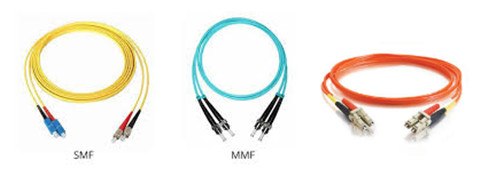
Besides the jacket color, the difference between multimode and single-mode optical fiber (9-mircon core) is that the former has much larger core diameter; much larger than the wavelength of the light carried in it. Because of the large core and the possibility of large numerical aperture, multimode fiber has higher "light-gathering" capacity than single-mode fiber. In practical terms, the larger core size simplifies connections and also allows the use of lower-cost electronics such as light-emitting diodes (LEDs) and vertical-cavity surface-emitting lasers (VCSELs) which operate at the 850 nm and 1300 nm wavelength (single-mode fibers used in telecommunications typically operate at 1310 or 1550 nm). However, compared to single-mode fibers, the bandwidth & distance product limit of multimode fiber is lower. Because multimode fiber has a larger core-size than single-mode fiber, it supports more than one propagation mode; hence it is limited by modal dispersion, while single mode is not.
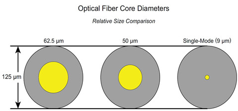
The light sources used in these two cable types also plays a critical role in the performances. The LED light source sometimes used with multimode fiber produce a range of wavelengths and these each propagate at different speeds. This chromatic dispersion is another limit to the useful length for multimode fiber optic cable. In contrast, the lasers used to drive single-mode fibers produce coherent light of a single wavelength. Due to the modal dispersion, multimode fiber has higher pulse spreading rates than single mode fiber, limiting multimode fiber’s information transmission capacity. Thus, single-mode fibers are often used in high-precision scientific research because restricting the light to only one propagation mode allows it to be focused to an intense, diffraction-limited spot.
Conclusion
The growth in subscribers’ demand for more sophisticated electronics and web-connected services increases the requirement for information storage and cloud technology. End-users also want to know how to choose the right cable type for your network application. Therefore , I hope after reading this article you might have learned something from it.
Posted by: fernxu123 at
07:43 AM
| No Comments
| Add Comment
Post contains 940 words, total size 8 kb.
December 20, 2016
With the technology evolving rapidly and new products keep coming out, optical technicians have to upgrade their knowledge accordingly. Take the UTP (unshieled twisted pair) network cabling as an example, lately telecommunication industry witnessed the evolution of copper cable from the old cat 3, cat 5 to the existing popular cat 5e and cat 6 cable (even to the cat 7 cable or cat![]() . Therefore, cable installers attach great importance on the TIA-568B installation. Even the experienced installer may discover the problems that they have never been aware of before. Today’s article is going to present all the detailed information necessary to complete a fully compliant TIA-568B UTP installation.
. Therefore, cable installers attach great importance on the TIA-568B installation. Even the experienced installer may discover the problems that they have never been aware of before. Today’s article is going to present all the detailed information necessary to complete a fully compliant TIA-568B UTP installation.
Overview of UTP Cable & TIA-568B Wiring Standard
Designed primarily for data transmission in local area networks (LANs), UTP network cable is a 4-pair, 100-ohm cable that consists of 4 unshielded twisted pairs surrounded by an outer jacket. Each pair is wound together for the purposes of canceling out noise that can interfere with the signal. So, remember to keep UTP cables as far away from potential sources of EMI (electrical cables, transformers, light fixtures, etc.) as possible. UTP cables should maintain a 12-inch separation from power cables.
In terms of the TIA-568B wiring scheme, this standard was published in 2001 to replace the 568A standard, which is now obsolete. The original purpose of the EIA/TIA 568 standard was to create a multiproduct, multivendor, standard for interoperable connectivity. The 568B standard sets minimum requirements for the various categories of cabling.
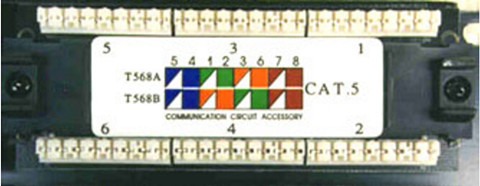
Figure 1 shows the wiring diagrams imprinted on the jacks. The upper diagram is 568A, and the lower diagram is 568B. We can clearly see the only difference between 568A and 568B is that pairs 2 and 3 (orange and green) are swapped. For detailed information about 568A and 568B, please read the previous article "How to Configure the RJ45 Pinoutâ€.
Do's and Don'ts of UTP Installation
Before you proceed the following article, you must understand that this article is for general information only. Always check with the local store or cabling consultants when planning a network cabling installation.
Things You Should Do
For the UTP cable, or all the copper cables, you take the following instructions seriously during the installation.
- Run all cables in a Star Configuration so that all network links are distributed from, or home run to, one central hub. Visualize a wagon wheel where all of the spokes start from on central point, known as the hub of the wheel.
- The UTP cable run must be kept to a maximum of 295 feet, so that with patch cords, the entire channel is no more than 328 feet.
- Maintain the twists of the pairs as close as possible to the point of termination, or no more than 0.5"(one half inch) untwisted.
- Make only gradual bends in the cable where necessary to maintain the minimum bend radius of 4 times the cable diameter or approximately 1" radius (about the roundness of a half-dollar).
- Dress the cables neatly with Velcro cable ties (see in the below image), using low to moderate pressure.
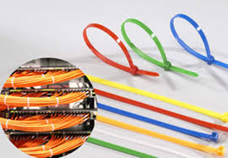
- Use low to moderate force when pulling cable. The standard calls for a maximum of 25 lbf (pounds of force). Install proper cable supports, spaced no more than 5 feet apart.
- Use cable pulling lubricant for cable runs that may otherwise require great force to install. (You will be amazed at what a difference the cable lubricant will make)
- Always label every termination point at both ends. Use a unique number for each network link. This will make moves, adds, changes, and troubleshooting as simple as possible.
- Always test every installed segment with a cable tester to make sure the attenuation under control.
- Always install jacks in a way to prevent dust and other contaminants from settling on the contacts. The contacts (pins) of the jack should face up on flush mounted plates, or left, right, or down (never up) on surface mount boxes.
- Always leave extra slack neatly coiled up in the ceiling or nearest concealed place. It is recommended that you leave at least 5 feet of slack at the work outlet end, and 10 feet of slack at the patch panel end.
- Always use grommets to protect cable when passing through metal studs or anything that can possibly cause damage.
- Choose either 568A or 568B wiring scheme before you begin your project. Wire all jacks and patch panels for the same wiring scheme (A or B).
- Always obey all local and national fire and building codes. Be sure to firestop all cables that penetrate a firewall. Use plenum rated cable where it is mandated.
Things You Can Not Do
You should never proceed the following steps, or you will end up with permanent damage to the geometry of the cable.
- Skin off more than 1" of jacket when terminating UTP cable.
- Allow the cable to be sharply bent, twisted, or kinked at any time.
- Over tighten cable ties or use plastic ties.
- Splice or bridge UTP cable at any point. There should never be multiple appearances of cable.
- Use excessive force when pulling cable.
- Use oil or any other lubricant not specifically designed for UTP network cable pulling as they can infiltrate the cable jacket, causing damage to the insulation.
- Tie cables to electrical conduits, or lay cables on electrical fixtures.
- Install cable that is supported by the ceiling tiles. This is unsafe, and is a violation of the building codes.
- Never install cables taught. A good installation should have the cables loose, but never sagging.
- Mix 568A and 568B wiring on the same installation.
In Closing
It is rare that we can directly use the patch cables or short link copper cable to connect the devices to the switch. In most cases, we need to install cable links to remote locations from patch panels to switch ports, which is far more complex. Therefore, anyone who install UTP cabling should take the dos and don’ts seriously. Any minor mistake can easily become a nightmare in the future.
Posted by: fernxu123 at
03:44 AM
| No Comments
| Add Comment
Post contains 1010 words, total size 8 kb.
December 14, 2016
Every enterprise or small business that needed a server was required to invest in its own infrastructure, hardware and maintenance solutions, with all the equipment accommodated in a dedicated room of the office. However, thanks to the cloud technology and the rapidly increasing availability of fiber connectivity, other options like data center have opened up in recent years. So how should you decide whether you will go with a data center service or a server room? To ease out the confusion, today’s article presents the differences between data center and server rooms.
Data Center & Server Room
Of course, every company has their own needs, and what works best for one company is not necessarily going to be the best solution for another. A server room is a room that devoted to store servers. A data center, to this purpose, is a whole building specially designed to contain and support a large amount of computing hardware of some sort.
The main difference between them is the size, but it is linked to design, scale and purpose. There will be several server rooms in almost any modern office building, but only very large companies whose business is about processing data will have data centers. The following part will continue to provide the detailed information about the pros and cons of each approach so you can determine what makes the most sense for you.
The Advantages and Disadvantages of Data Center
Pros—If you are just starting up your business, you may find it valuable to keep your network systems in a data center as you can enjoy and provide the same services to other companies to keep your costs down. As for the maintenance responsibility, every data center has the redundant backup system for network access, electricity and climate control, so you are not very likely to experience the network outage. Even in the case of a local power utility outage, they remain up and running owing to the backup power generators. Figure 1 outlines a brief diagram of data center solution.
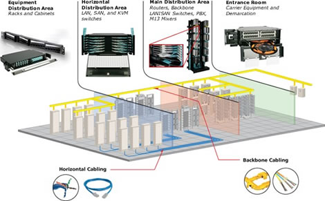
Another unique feature of the data center is that enterprises appreciate the colocation model, which allows you to bring you own hardware to the shared facility. Depending on the nature of the data center, you may or may not have the ability to determine when your scheduled maintenance down times will be, and you may or may not be able to choose what hardware is being used for your server stacks.
Cons—Although data center possesses all the above advantages, you can’t miss the point of finical burden involved with infrastructure and maintenance as well as the upfront costs for moving to a data center. Particularly if you opt for a colocation data center, where you provide both hardware and software, there may be major spending involved. Even if the data center provides all of these resources, you have to pay the initial subscription and setup fees. What’s worst, over time, these fees may begin to feel negligible, especially as compared to the ongoing cost of an in-house server stack.
When you remove your server from your premises, you're going to lose a certain degree of potential for in-house oversight and control. If you completely outsource your server stack, you end up being fully dependent on the data center for maintenance, security and uptime. This may well be to your advantage, but many prefer to be less dependent on remote third parties.
The Advantages and Disadvantages of Building a Sever Room
Pros—Just as Figure 2 shows a server rooms with all the hardware and software located in a dedicate room of office, it means you completely own the server facility. All of the responsibility falls on you, but in exchange, you get to enjoy all of the benefits that only your company can control. You'll be the sole manager of your own facilities, and you can modify your system on your own terms, to accommodate any shifting needs, including expansion as your business scales up. That kind of versatile customization can be particularly useful if your system is unusually complicated, large, or includes many diverse applications.
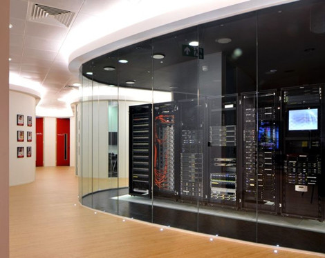
The security issues also all comes down to you, which grants you control over your system in a way that moving it offsite cannot provide.
Cons—All the responsibility of the server room falls on you, but at the same time, you have to devote all your heart and energy to it, which is far beyond the substantial workload. First of all, you may need your IT team to focus on initiatives that related to your business, and the ritual maintenance of the health of the server stacks and physical infrastructure. Their attention will be split, then it will end up with work failure.
Another downside about sever room is that the backups is less effective especially when your data is stored in one physical location. In the event of theft, fire, flood or other disaster, you could end up losing everything with no recourse for recovery. Keeping your network local, moreover, makes it harder to expand your business to new locations. When you do open up new branches, you'll need to find good solutions for everyone to connect to headquarters, instead of both locations connecting to a facility that's made for offsite networking, which is the case with data centers.
Upfront costs is significant when you invest in your own onsite servers, and you won't have any way of knowing from the get-go how much capacity for growth you need to account for, so you'll end up purchasing a system that's either more powerful than you need or that isn't able to grow as your data needs expand.
Which One is Best for You?
After going through the whole passage, I bet you might have made up you won mind of whether to make use of a data center or to opt for your own server room. Many factors you should take into account—budget, your network scale & future proofing, but sometimes it is just a matter of personal preferences. The best way to make the decision, therefore, is to consult with an expert who can assist you in determining given the specifics of your case. FS.COM offers a full range of data center solutions that can be also used in server rooms like the patch panels, fiber enclosure, cable manager, fiber optic cable and transceivers. If you have any requirement, please send your request to us.
Posted by: fernxu123 at
03:35 AM
| No Comments
| Add Comment
Post contains 1084 words, total size 8 kb.
December 07, 2016
2017 is coming in less than a month, looking back, in the communication field, the old remaining dilemma between fiber and copper is still left behind. People are struggling about whether they should hold on to the tried-and-tested copper cables that are sufficient so far, or make the leap into the future, and go fiber optic. From a technical perspective, the case for switching to fiber is growing ever stronger. Using a fiber system will lead to more bandwidth, reliability, less down time and end up saving you money. Today’s article will make you understand the trend for switching to fiber.
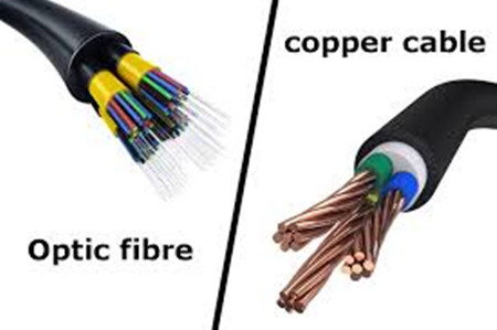
More Bandwidth, Faster and Longer
People are aware that fiber optics is winning out over copper because of its higher performance, namely more bandwidth, faster speed and longer link distance.
Bandwidth decides how much data you can receive and send. Copper cable that can be used for 10 Gigabit cabling, and 100 Gigabit cables is at the point of topping out, but these data rates can be sent only for very short distances between servers in data centers. While with fiber you can transmit more data over greater distances, and if you’re preparing for fiber now, you’ll also start to see remarkable differences in the not too distant future.
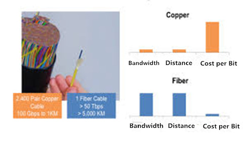
Have you ever though of the reason why fiber can transmit at higher speed for longer distances then copper cables? In short, copper cable uses the electric waves to carry the signal data, the phrase of the wave are modulated in sophisticated patterns to try and send as much data as possible through the continuous signal. This works well for low amount of data, but the copper cable will start to break down if you get to higher bandwidths and greater distances. As for fiber cable, it uses light to carry signals with transmitters and receivers at both ends. Light loses much less power than an electrical signal, so fiber can send data over much greater distances.
Fiber is More Reliable Than Copper
Besides the above reasons, another big reason that makes enterprises choose to use fiber other than copper is the reliability of the fiber optic system. If you put too many copper wires in close proximity, or just put them near any significant power sources, the signals can be easily interfered and read by others. Brazilian E-Voting machines were compromised using Van Eck Phreaking, with hackers able to read secret votes through these side-band electronic-magnetic emissions from the machines.
But fiber doesn’t suffer from the same problems as copper, so maintenance issues are rare. You can put multiple fiber optics next to each other and there won’t be any interference, and you can route them wherever in your building and they’ll still work perfectly. In fact, fiber can be routed through a building near power line conduits without any degradation of the signal. Therefore, it is not the good choice to still stay at copper wire because of its crosstalk where data from one wire gets mixed up with data on another.
Fiber is Safer
There are also safety issues, for people and equipment, with copper cabling which are no doubt at the forefront of your tech’s mind when they are telling you to go for a fiber installation. Any misconfiguration of your system, or out of the blue power surge, and having everything wired together with copper suddenly becomes a serious problem. For example, a lightening strike jumped through copper cabling between buildings, can destroy all the electrical equipment in both buildings.
Light doesn’t leak, and if it does you’ll know about it. Someone splicing into the fiber will leave a tell-tale signal as the attenuation will drop, just as when fiber is damaged. Using a testing technique called optical-time domain reflectometry, you can easily find where someone has spliced into the system and hunt the spies down!
In general, it’s also easier to test if something does goes wrong. The way light travels through glass is better understood than how electricity flows through copper, so any diagnostics are straightforward.
Fiber is More Flexible Than Copper
Fiber optic cable is composed of a thin, flimsy strand of glass, which is very delicate, needing installation by specialists in white gloves. And it can be destroyed by any clumsy-fingered techie thereafter. However, it is stronger than copper cables (made of a thick cord of metal).
Even though the fiber optic cable is lightweight and thin, it can be pulled through buildings with more force than copper, and can take a dunking in water, and is more flexible so can negotiate tricky building geography. All the while being lighter and thinner than copper, so it can be installed with more ease anywhere in your building.
Because it’s so lightweight and thin, it takes up less space, and is easier to handle. If you want to scale a copper wired system then you need more and more of bigger and bigger cabling. With an optical system, there is almost no difference in size between the diameter and weight of different size fibers, and because a smaller fiber can carry so much more data than copper cables, you need less overall.
Fiber Will Cost You Less
When people suggest you switching to fiber, you might not think that they take budget into account, but in the long run, fiber optic system will cost your company less.
Because fiber is more resilient, there is less downtime on the network. Because of all the maintenance and legacy issues with copper wires, you’ll always have downtime while an ISP technician is down a manhole somewhere splicing together copper cables that have been damaged.
There’s also less hardware to go with the fiber optic system. Because data can be transmitted over fiber for longer distances, you don’t need the extra power boosters, junctions, and terminals that are needed for copper cabling. Your fiber can be brought directly to your office with no need for multiple connections.
Fiber is new technology that is constantly evolving and a hot area of research. We believe that in 2017, fiber optic based system will be more popular among users.
Posted by: fernxu123 at
02:20 AM
| No Comments
| Add Comment
Post contains 1026 words, total size 8 kb.
December 02, 2016
We usually use terms—CMP, CMR, PVC and LSZH to describe telecom cables, but do you know what these terms really mean? And, more importantly, which one does your project actually need? The article below will briefly outline many industry cable types, along with their features to help you have a better understanding of them.
Plenum Rated Cables
CMP cable refers to the communication plenum cable that is laid in the plenum spaces of buildings. Plenum rated cable or just plenum cable is jacketed with a fire-retardant plastic jacket of either a flame retardant low-smoke polyvinyl chloride (PVC) or a fluorinated ethylene polymer (FEP). Owing to its material in this network cable, it doesn’t emit a toxic smoke when they burn. Plenum rated cables are slower to burn and produce less smoke than other cables.
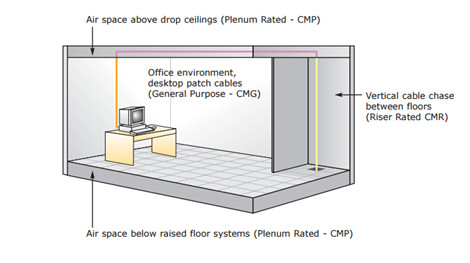
As seen in the above image, plenum refers to the air handling space. In a standard commercial building, the plenum is the space between the drop ceiling and the structural ceiling. In residential installations the plenum may include the space above the ceiling or under the floor when floor level air circulation is used. Plenum rated cable is mandated to be installed in any "air handling†space because of its low smoke and low flame characteristics.
Riser Rated Cables
CMR cable refers to the communication riser cable that is run between floors in non-plenum areas. The term â€riser†usually refers to a space that runs between floors in an office or a commercial building. The fire requirements on riser cable are not as strict as plenum cables. It will emit toxic fumes when burning. This is considered to be a slight problem, but it is not enough to warrant consideration as long as these cables are not used in ducts.
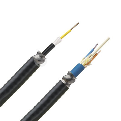
These cables can be used for both commercial and residential spaces but are generally used more for residential homes. For example, riser cables can be used from room to room, as long as it is run around baseboards, along bottoms of walls, and along the tops of walls. They can also be used to run cables from the basement to the upper floor, as long as the cable does not need to pass through an air duct.
How Do I Know Which One Should I Choose?
Many customers has asked about this question, unfortunately we cannot help or advise you as each individual cabling details has to be evaluated. However, for those who plans to wire their house with cat 5e or cat6a cable, we do have some practical suggestions for you to choose between plenum and riser rated cables.
Both plenum and riser cables commonly include a rope or polymer filament with high tensile strength, which helps support the weight of the cable when it is dangling in an open chute. Cables like twisted-pair, coaxial, HDMI, and DVI are available in both plenum and riser versions. The cable cost is often significantly higher than general-use cable due to the special restricted-use flame retardant materials. Plenum cable is expensive, much more expensive than riser rated cable. Additionally the practice of running cables in plenum spaces is becoming less popular, and therefore demand for plenum rated cable is much less than riser rated cable.
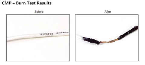
However, the plenum rated cables have a higher fire rating than riser cables. Thus, plenum cable can always replace riser cable, but riser cable cannot replace plenum cable in plenum spaces. The stiffness of CMR cable is less than that of CMP cables. This means CMR cable is easier to bend around corners of baseboards and ceilings. This can allow a tighter fit against corners to minimize the look of cables. The following two pictures shows the burning test of these two cables.
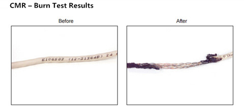
One final tip to keep in mind is that If you will never need to run it through air-handling ducts/spaces, just get Riser rated. But, for retrofits, that's often the easiest route from basement to the upper floors and sometimes a few basement ceiling joist spaces are covered over with tin to use as inexpensive cold air return ducts. If you have to go through those, Plenum rating is required, too. If there's ever a hot enough fire to melt CMR's covering, any toxic fumes it might emit will be among the least of your worries. but the Riser rating means its fire-resistance will keep the flames from following it between floors.
Conclusion
Selecting the right type of cable for your home network is important; CMP cable is usually recommended as it is safer to use in case of fire, even though they are more expensive and stiffer than CMR cabling and more difficult to bend. But if you are not up to run cables through air duct, CMR cable is actually a great choice, as this type of cable is less expensive and easy to install in a network. FS.COM is committed to offer the most cost-effective cabling solutions to our clients. Our cat 5, Cat 5e, cat 6 cables are available in both plenum and riser version. If you have any interest, please feel free to visit fs.com.
Posted by: fernxu123 at
06:54 AM
| No Comments
| Add Comment
Post contains 857 words, total size 7 kb.
November 29, 2016
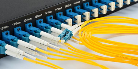
Several years ago, OS1 fiber optic cable was the only one standard for single-mode fiber with the maximum link length for campus cabling around 10km, but 10km can no longer satisfy people’s increasing needs nowadays. Therefore, OS2 fiber that can support much longer distance than 10km has been widely utilized in telecommunication industry. But there has been some debate and confusion as to the differences between OS1 and OS2 fiber types and what the terminology actually means. Thus, the following article is provided to assist the users in understanding the differences between OS1 and OS2 fiber types. The following image shows the LC to LC fiber patch cable single mode plugging in a switch.
OS1 and OS2 Single-mode Fibers
Firstly, OS in the term OS1 and OS2 specifications refers to the Optical Single-mode fiber. Single-mode OS1 is indoor tight buffered fiber. An OS1 cable could be a micro-core LSZH indoor cable that consists of 250 micron fibers, with the fibers being tightly enclosed in a cable with aramid strengthening yarn and a LSZH jacket. The attenuation of a OS1 fiber is higher than an OS2 fiber. From the above table, the maximum attenuation allowed per km of installed cable is 1.0 dB for OS1 for 1310nm and 1550nm, while the maximum attenuation allowed per km of installed cable is 0.4 dB for OS2 for 1310nm and 1550nm.

Single-mode OS2 is an outdoor loose tube optical fiber cable, which is suitable for outdoor applications where the cabling process applies no stress to the optical fibers. For instance, a 250 micron coated multi-fiber, which is loose inside an enclosure or tube and/or is free to move, is classified as OS2.
OS1 or OS2 performance cables are constructed from B1.3 optical fibers (or ITU specification G.652D). Furthermore, OS1 and OS2 cable types can also include cables manufactured from B6_A fiber, which is commonly known as bend insensitive single-mode optical fiber, or ITU specification G657A2 (compatible with B1.3 optical fiber). OS1 or OS2 single mode fiber performance, does not relate to ITU specification G.655 (Non-dispersion shifted single mode optical fibers.
Why Should We Use OS2 Over OS1 Fiber?
Single-mode fiber was mainly used for long-hual applications but not marked as a cost-effective investment for future application in building. One reason is that the single-mode related products like cables and optical transceivers are offered with high price. The other is that with the price decrease of the VCSEL or laser power source, the performance gap (namely link length) between multimode or single-mode fiber is smaller everyday.
Considering this, why not use the best single-mode fiber (OS2) to create better performance and ready for high speed data networks? Besides the difference in link distance, OS1 and OS2 fibers have different attenuation—OS2 has two times less losses than OS1 fibers. And in CWDM or DWDM network, OS1 has poor result in the wavelength range called E-band or water peak band, which makes it not suitable for the WDM-based network.
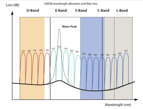
Figure 3: CWDM wavelength allocation and fiber loss. The solid line represents OS2 fibers. The dotted line represents the water peak.
Another good news is that if you use OS2 fiber, it will be more suitable for you to support the IEEE 802.3 multiplexed series (40G BASE-LR4 and 100G BASE-ER4). You even don’t need to change your existing OS1 fibers, as the OS2 can be mixed with OS1 in the same link. What’s more, active or passive component for OS1 like connectors, adapters also works with OS2.
Conclusion
To sum up, OS1 optical fiber is appropriate for indoor and universal tight buffered cable constructions, which are mainly deployed in internal building/campus networks, as well as internal cabling within telecommunication exchanges and data centers. While OS2 optical fiber is appropriate for outdoor and universal loose tube solutions, which would include external plant and most back-haul networks. Therefore, when deciding which single-mode optical fiber type to specify, consider the application as well as how and where the cable will be installed. For further information on optical fiber products, please contact FS.COM. Our fiber optic cable price is the cheapest with great feedback.
Posted by: fernxu123 at
08:41 AM
| No Comments
| Add Comment
Post contains 690 words, total size 6 kb.
November 18, 2016
It is a pretty expensive process to set up a home network since you need to purchase all the related devices (router, switch, modem, Ethernet cables and so on) and hire a seasoned optical technician to do the cabling job. But bear in mind that there is really no such things as the perfect home network—what works for you will depend entirely on your individual needs and the devices you use. From time to time, we hear from people who plan to install Ethernet cables (cat 5e or cat 6 cables) in a home network, but they don’t know what Ethernet cable is vital and what they can do without. Therefore, this article offers some suggestions to help you run Ethernet cables with all the hardware, and prevent you from cable spaghetti.
HOME NETWORK
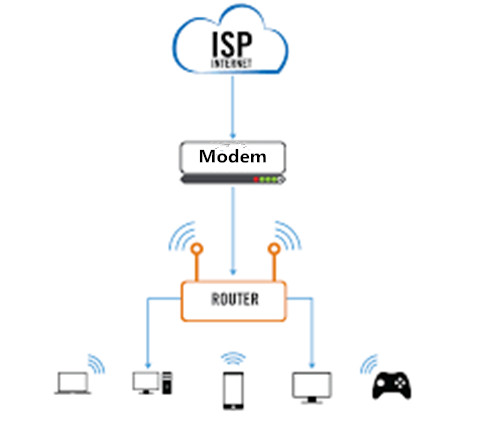
As you can seen in the below image, a simple network usually consists of modem, router and Ethernet cables. Modem works just like the "gatekeeper†between your ISP and your home network, connects to cable or DSL wall outlet. And the router is like the "traffic control†that routes data traffic and broadcasts Wi-Fi. Ethernet cables is mainly used to connect your modem to your router. Also connects stationary devices to the router. Note that if you need more ports, a switch might be a better choice than router. The next part will focus on how to choose the Ethernet cables for a home network.
What’s the difference between Cat 5e and Cat 6 cable, and which should I use? In fact, the choice of the best Ethernet cable depends upon several factors including the Internet connection speed, the capabilities of connected devices and the cable lengths.
Factors When Selecting the Ethernet Cable
- Cable Capacity
Ethernet cabling differences can be invisible to the casual observer. However, each new generation introduces copper pairs with tighter twists and more complex sheathing. Many earlier Ethernet generation cables have become obsolete like the cat 3 cables. The following chart shows the difference between them.

The commonly available Ethernet cables range from Cat 5 to Cat 6a, although a higher specification Cat 7 cable is also available. Cat 5 and Cat 5e cables are designed to operate at 100 MHz and are suitable for Internet speeds up to 100 Mbps (100BASE-T). However, Cat 5e cable has lower crosstalk thanks to minor improvements in the manufacturing process and can also be used for 1 Gbps Internet.
Cat 6 cable has more stringent specifications than Cat 5e cable and is capable of operating at 250 MHz. It has slighter thicker wires, and the cores are more tightly twisted together. This means the cable is thicker and less flexible than Cat 5e cable. Its performance on 1 Gbps Internet is better than Cat 5e, and it's suitable for 10 Gbps service to a maximum distance of 180 feet. Cat 6a cable has improved properties and can operate at 500 MHz and can support 10 Gbps (10GBASE-T) to a maximum distance of 328 feet. It should be noted that cable termination requirements for Cat 6 and 6a cable are stringent, and the cable requires better protection than Cat 5e cable.
Cat 7 cable is designed for extremely high Internet speeds of 40 Gbps and 100 Gbps, but is of limited application as the technology is still being developed.
- Internet Connect Speed
Before selecting an Ethernet cable, it's essential to establish the maximum capabilities of each piece of equipment because the actual speed will be determined by the slowest device. The actual speed of the Internet connection should also be verified because this is rarely as fast as advertised. Also remember that the link speed is influenced by the distance between switches.
- Use Cables Suitable for the Environment
In the industrial environment, you have to make sure the cable you use has the physical integrity necessary for the job. Harsh conditions are the norm; conditions such as shock, vibration, crushing and extreme temperatures routinely occur. Plus the cable may need to withstand intrusion from elements such as chemicals, water and debris. For examples, Flexible flat cables are more preferable than the round ribbon cables for hand held devices, automation and robotic applications.
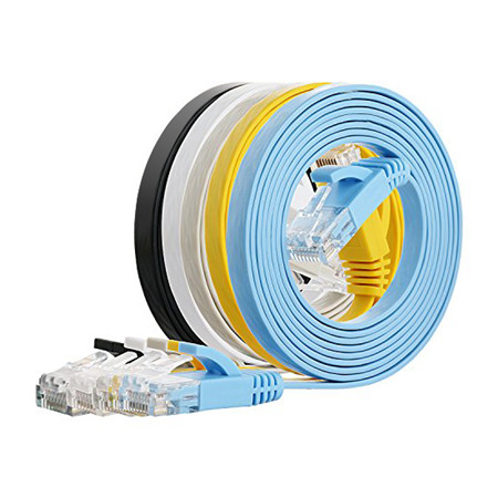
In addition, regulations exist to define the tolerances that the cable must meet for a variety of applications where reliability or safety is an issue. The regulations vary by industry and by geography, thus you want to make sure you have the right cable for the particular project.
Make the Final Decision
Both the cat 5e cables and cat 6 cables are available for your home network, but the best Ethernet cable must be the one that meets the current and anticipated Internet connection speeds at the lowest cost. Bear in mind that Cat 6a cable costs significantly more than Cat 5e cable and that installation requires more care and takes longer.
However, if the requirement is for ultra-fast Internet and the distance between switches exceeds 108 feet there's no question that the best cable is a Cat 6a. But if the cable lengths are short, or the connection speed doesn't exceed 1 Gbps, a Cat 5e cable is a better choice due to its lower cost, robust construction and easier installation. Although Cat 7 cables may offer superior performance, the additional cost doesn't warrant their use except for very specialized applications. If you want to find more detailed information, please visit fs.com.
Posted by: fernxu123 at
03:16 AM
| No Comments
| Add Comment
Post contains 909 words, total size 7 kb.
November 16, 2016
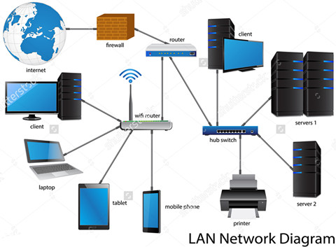
Local area network (LAN) is the smaller network, usually within an office base or inside one building, which is used to connect computing resources including the computers, printers, servers, IP phones, or gateways. Connections within the LAN network are physical with cables, and all the office resources are shared and distributed between the network workstations. The most common type of LAN is the Ethernet—a family of frame-based computer networking technologies. But do you know how to set up a LAN system? What do you need while setting up the LAN network?
It is not a simple project to set up a LAN network (seen in the below image), especially for a beginners in telecom field. Thus it is advisable to make a comprehensive plan before making the next move. Network components like cable router, Ethernet cables, Ethernet switch and Network interfaces are the basics of a LAN network. Computers are connected to a switch with Ethernet cables. Make sure cable lengths do not exceed 100 meters, or about 300 feet. Each device are supposed to have a unique IP address. Besides that, you must first identify which services you need to provide locally on the LAN. The next part will move on to give you some detailed instruction about setting up a LAN network.
Six Instructions to Set Up LAN Network
Step 1. Identify the local services that you want available on the network. Identify network-attached printers, network disk drives, any server that will share printers or disks. Identify how many devices will have to connect to the network. Each device, server or workstation will require a unique address.
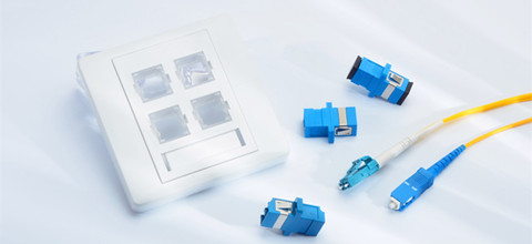
Step 2. Do not run cables in air ducts unless they are fire rated. A wired LAN will always get better performance and be more secure than a wireless LAN. Wherever possible, run a cable to servers, printers, IP phones or work locations. Run a cable to any area where you are likely to work. Use standard Ethernet cables like the cat6a cable or building wiring as installed according to the TIA-568 standard. The accessories like fiber optic wall plates, fiber patch cables, optical connectors are small but indispensable for a high performance LAN network just as seen in the below image.
Step 3. Use a switch or router with wireless capacity gives you more flexibility. The simple secure way to connect to the Internet is to use a cable router. Many types and models are available. If the model you choose does not have enough ports to connect all of your computers, then you will need to purchase a switch as well. Also a wireless router is needed in a modern LAN network.
Step 4. Configure the LAN ports of your cable router. Most cable routers will act as a Dynamic Host Configuration Server, or DHCP server. This means that the router will give addresses to workstations automatically. Be certain that the address pool has enough addresses for all of the workstations. Make certain that there are enough addresses outside of the range for any hosts that need static addresses. For example, a network address with a mask of 255.255.255.0 has a total of 254 hosts. If the dynamic pool has 200 addresses available, that means the remaining 54 addresses are available to give printers or servers static addresses.
Step 5. Connect the wires for the network. Workstations and servers can be connected with standard Ethernet cables. Connect the switch to the cable router LAN ports by using the up-link or straight port on the switch. If the switch does not have an up-link port, connect any standard port of the switch to a LAN port on the cable router with an Ethernet crossover cable. Ethernet crossover cables can be purchased at any electronics store.
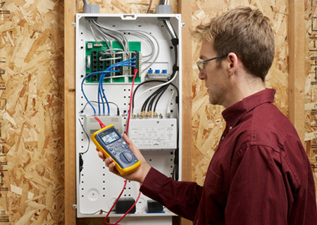
Step 6. Test the services and Internet connectivity. The actual performance of LAN network depends upon numerous factors including the cable specification, the quality of the installation and the connected devices. For this reason it is not sufficient to assume an installation will perform at the desired speed; its actual performance should be checked. It is advisable to test each of the workstations to ensure they can connect to the Internet and test any local servers and printers. Print test pages on the shared printers. Tests read and write permissions on shared file servers by copying files to the servers and copying files from the server to a workstation.
Conclusion
Although the above practices are a good starting point, there are no real one-size fitting all solutions as every small office is unique and has it own features. What matters when building a LAN network is how well you can assess your needs and pair them with the networking hardware that is available within your budget. FS.COM offers a series of optical devices including the Ethernet cables (Cat 5e cable, cat6a cable, cat 7 cable), fiber optic wall plate, optical connectors and cable testers. Our best buy ethernet cable is provided with high quality and great feedback. If you have any needs, you can have a look at our website.
Posted by: fernxu123 at
03:21 AM
| No Comments
| Add Comment
Post contains 852 words, total size 6 kb.
November 04, 2016
Cisco Small Form-Factor Pluggable (SFP) transceiver can be defined as a device that comprises of both a transmitter and a receiver of analog or digital signals. It is a compact, hot swappable, input/output device based on the available fiber cable type (copper cable or multimode/single-mode optical fiber). In addition, SFP transceivers can be leveraged both at 100Base and 1000Base rates in the following standards:

SFP transceivers are mainly used to link equipment in telecommunication and data communications like switches and routers. They support applications like 2G/4G Fiber Channel, SONET/SDH Network, Gigabit Ethernet, High-speed computer links, and with CWDM and DWDM interfaces. Today’s article will generally introduce the Cisco SFP transceivers including the Cisco 100M SFP, Cisco 1000BASE SFP, CWDM/DWDM SFP, SONET/SDH SFP as well as Cisco BiDi SFP to you.
Cisco 100Mbqs SFP
Cisco offers two different types of 100BASE SFP—100BASE SFP for Fast Ethernet (FE) SFP Port and 1000BASE SFP for Gigabit Ethernet (GE) port. Besides the above standards, the Cisco 100BASE SFP portfolio includes 100BASE-FX, 100BASE-LX, and 100BASE-BX SFPs.
Cisco 100BASE-FX SFP operates on MMF for link spans of up to 2km. 100BASE-LX SFP operates on SMF up to 10km. 100BASE-BX SFP operates on SMF for a link length of up to 10km. A pair of a 100BASE-BX-D and a 100BASE-BX-U SFP is needed for the single strand deployment. The following table displays the compatible Cisco 100M and 1G SFPs from FS.COM.
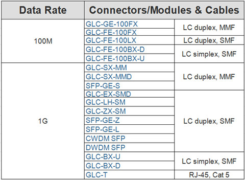
Cisco 1000BASE SFP
Cisco 1G SFP transceivers offer a convenient and cost-effective solution for the adoption of Gigabit Ethernet and Fibre Channel in data center, campus, metropolitan area access and ring networks, and storage area networks. They are available in several Gigabit standards—1000BASE-T, 1000BASE-SX, 1000BASE-LH, 1000BASE-EX, etc. Take Cisco GLC-LH-SM as an example, it operates over standard single-mode fiber spanning distances of up to 10 km and up to 550 m over any multimode fiber (OM3/OM4). If 1000BASE-LX/LH SFP transceiver transmits in the 1300nm wavelength over OM1/OM2 fiber, it requires mode conditioning patch cables.
Cisco CWDM/DWDM SFP Modules
Cisco Coarse Wave Division Multiplexing (CWDM) solution allows scalable and easy-to-deploy Gigabit Ethernet and Fibre Channel services. Similar with traditional SFP module, the Cisco CWDM SFP is a hot-swappable input/output device that plugs into a SFP port or slot of a switch or router. CWDM SFP transceiver modules make use of the SFP interface for connecting the equipment and use dual LC/PC fiber connector interface for connecting the optical network with a link distance of up to 80km. It usually comes in 8 wavelengths covering from 1470 nm to 1610 nm. Color markings on the devices identify the wavelength to which the Gigabit Ethernet channel is mapped. The following picture lists the FS.COM compatible Cisco CWDM SFPs with their wavelengths and color codes.

DWDM (Dense Wavelength-Division Multiplexing) SFP transceivers, however, are used as part of a DWDM optical network to provide high-capacity bandwidth across an optical fiber network. Cisco DWDM SFP is a high performance, cost effective module for serial optical data communication applications up to 4.25Gb/s. There are 32 fixed-wavelength DWDM SFPs that support the International Telecommunications Union (ITU) 100-GHz wavelength grid.
Cisco SONET/SDH SFP Modules
This Cisco SONET/SDH SFP is compatible with the SONET/SDH standards, and support the digital diagnostic functions specified in the SFF-8742 Multi-Source Agreement (MSA). Cisco SONET/SDH SFP can be directly plugged into a variety of ports on Cisco router interfaces. These SFP optics support OC-3, OC-12, and OC-48 data rates for multimode, short-reach, intermediate-reach, and long-reach (up to 80 km) applications just as seen in the below chart.
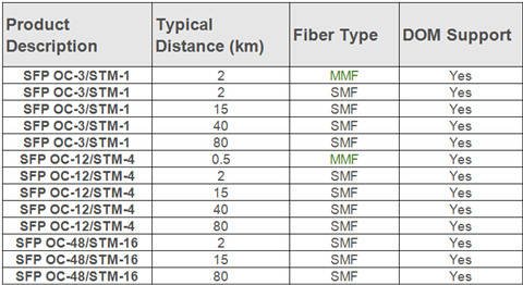
Cisco BiDi SFPs
Bidirectional (BiDi) SFP transceivers can transmit and receive data to/from interconnected equipment through a single optical fiber. BiDi transceivers are fitted with wavelength division multiplexing (WDM) diplexers, which combine and separate data transmitted over a single fiber based on the wavelengths of the light. BiDi transceivers must be deployed in matched pairs, with their diplexers tuned to match the expected wavelength of the transmitter and receiver that they will be transmitting data from or to. These transceivers offer bi-directional data links over single-mode fiber up to 120 km.
Take 1000BASE-BX SFP BiDi transceiver as an example, 1000BASE-BX SFP modules are compliant with SFP Multi-Source Agreement (MSA) specification and SFF-8472, and conform to the IEEE 802.3ah 1000BASE-BX10 standard. 1000BASE-BX SFP modules include 1000BASE-BX-U SFP module and 1000BASE-BX-D SFP module. The 1000BASE-BX-D SFP operates at wavelengths of 1490nm TX/1310nm RX, and the 1000BASE-BX-U SFP operates at wavelengths of 1310nm TX/1490nm RX. These transceivers use standard simplex LC connectors for fiber cable connection and provide a long transmission distance of up to 10 km.
Conclusion
It is necessary to select the suitable SFP transceivers for your network. This article has concluded several types of Cisco SFP transceivers, which might be a great help for those who are looking for Cisco SFPs. FS.COM, a leading and professional fiber optic SFP transceiver module provider, has a large inventory of 1000BASE SFP, 100BASE SFP, CWDM/DWDM SFP, BiDi SFP, etc. If you have any needs of our transceivers, please send your request to us.
Posted by: fernxu123 at
02:29 AM
| No Comments
| Add Comment
Post contains 840 words, total size 7 kb.
October 27, 2016
With the top trend for data center and enterprises to move to higher data rate like 40G, relevant products and technologies are developed to back this new speed (e.g. the 40G optical transceivers and cables). However, there are so many options out there on the market. Network users usually don’t know how to make a choice. Take the 40G cables as an example, the most commonly used 40G cables are the 40G direct attached cable (DAC) and active optical cable (AOC). Each has its unique specification and usage. Which would be the most suitable one for connecting signals across the rack in data center? This article will provide you an ideal answer from the aspect of cabling performance, transmission distance and cost.
Brief Overview of DAC and AOC Cables
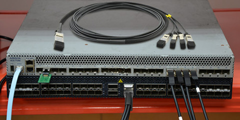
QSFP DAC cable is a form of high-speed cable with "transceivers†on either end used to connect 40Gbqs switches to routers or servers. QSFP+ DAC cable usually comes in either active or passive versions. They are widely available for short-reach 40G interconnect (within 7 meter). 40G DAC cables transmit 40GbE over short distances of parallel coaxial copper cabling. It uses a special cabling assembly with four lanes of coaxial cabling. Each transmit 10 Gbps for a total data rate of 40 Gbps. QSFP to QSFP and QSFP to SFP+ cable are the two common types of 40G DAC cables. The picture below shows a QSFP to SFP+ DAC breakout cable connected in a switch.
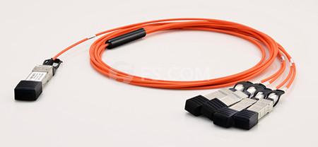
AOC cable uses electrical-to-optical conversion on the cable ends to improve speed and distance performance of the cable while mating with electrical interface standard. Compared with DAC cables, its smaller size, longer transmission distance, lower insertion loss and electromagnetic interference immunity make it popular among subscribers. 40G AOC cables (see in the image below) can support longer distance than QSFP+ DAC cables (within 15m).
Comparison Between DAC and AOC Cables
After the brief introduction to the DAC and AOC cables, what to be considered next is the detailed comparison from the expects of cost, distance and cabling performance. The following chart shows a vivid comparison between them.
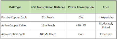
Cost
Cost is typically the No.1 factor affecting your selection. When it comes to 40G DAC cables, it is the same, although it’s quite clear that copper is much cheaper than optical cable. AOC, with connectors embedded with electronics and/or optics is the most expensive one. But it supports the highest transmission distance, many data centers won’t choose it because of the high cost.
While passive copper cable is much cheaper than AOC. However, the truth is that it cannot support 40G transmission in most cases in data center. Active copper cable is less expensive than AOC and can support longer transmission than passive copper cable seems to be a good choice. In this battle over cost, passive copper cable wins. But it is not suggested for 40G transmission in most cases.
Power Consumption
The main reason why DAC active copper cable and AOC can support longer transmission distance than passive cooper cable is that they are supported with active electronics. Passive copper cable requires no power. For 40G transmission, the power required for active copper cable is about 440mW, which is much less than that of AOC—2W. Thus, passive copper cable wins for its low power consumption.
Cooling System
Cooling is always crucial for data center, as it is closely related to the data center reliability and life of use. During DAC cable selection, two main factors can affect the cooling of data center. One is cable size. the other is the power consumption of direct attached cable. For the former factor, the thinner the cable is, the better dispersion devices in data center would have. AOC cable is the thinner than DAC cables. And DAC active copper cable is also thinner than passive cooper cable. The relation between power consumption and data center cooling is easy to understand. Higher power consumption can generate more heat in data center, which will load more burden on the data center cooling system. As mentioned before. AOC cable needs the highest power and DAC passive copper cable needs the lowest.
Transmission Distance
In the past, when the data rate required is less than 5 Gbps, the passive copper cables are used for interconnection. This type of DAC connects two SFP connectors by a copper cable, providing direct connection between cable ends via copper wire. Thus they are not expensive and robust with reliability. As it is passive, they need no power generally. However, when it comes to 40Gbps, they cannot satisfy such data rate in most cases. The passive copper cable with QSFP connectors attached on both ends can only support transmission 40 Gbps over very short distance. Thus passive copper cable is not suggested for regular 40G interconnection, unless 40G transmission is in very short distance.
Then AOC cable is introduced to overcome this challenge. Optical cables are thinner, flexible and can reach much longer distance up to 100 meters or more, which is much longer than that of the passive copper cable. However, AOCs are usually very expensive with the connectors attached on the active optical cable are embedded with optics and/or electronics. The connectors of the DAC active copper cable are embedded with electronics. Although they cannot support transmission distance as long as AOC, active copper cable can support longer transmission distance than that of the passive copper cable via copper wire. 40G transmission distance of active copper cable is about 15 meters.
To sum up, if you have a special requirement of the transmission distance. Then active optical cable wins with a transmission distance up to 100 meters. The active copper cable got the second place. And passive copper cable is at the last place. It is only suggested for 40G transmission over really short distance.
Conclusion
After comparing the performance of the DAC and AOC cables, we understand that the DAC passive copper cable is only suitable for really short-reach applications. While AOC cable possesses the best transmission performance but with higher cost in both material and daily use, and it needs more power as well. As for the DAC active copper cable, it can can support 40G transmission up to 15 meters with low power consumption, and satisfy the regular interconnection requirement for distance and cooling in most data center. What’s more, it is less expensive. FS.COM offers a full range of 40G QSFP cables including 40G DAC cable and AOC cables. Besides, the QSFP transceivers are also provided.
Posted by: fernxu123 at
03:49 AM
| Comments (1)
| Add Comment
Post contains 1091 words, total size 8 kb.
October 25, 2016
Fiber optic cable is considered as one of the most effective transmission medium today for safe, and long-reach communications, and it also offers a number of advantages over copper. In general, fiber optic cable consists of a core, cladding, coating, strengthening fibers, and a cable jacket, which has been clearly introduced in the previous article. Today’s article will focus on the several materials in fiber optic cable construction, as well as their features and applications.
PVC (Polyvinyl Chloride)
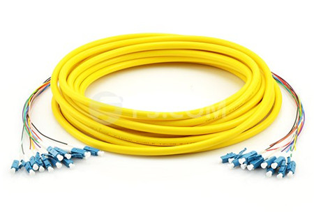
Polyvinyl Chloride (PVC) is one of the most commonly used thermoplastic polymers in the world. The PVC cable is typically used for patch connections in the data center, wiring closet, and at the desktop. PVC is produced in two general forms, first as a rigid or unplasticized polymer (RPVC or uPVC). The following image shows a ST single-mode pre-Terminated cable (0.9mm PVC Jacket).
Features:
- Good resistance to environmental effects. Some formulations are rated for -55 to +55.
- Good flame retardant properties. Can be used for both outdoor and indoor fiber optic cables.
- PVC is less flexible than PE (Polyethylene).
PE (Polyethylene)
Polyethylene is a kind of polymer that commonly categorized into one of several major compounds of which the most common include LDPE, LLDPE, HDPE, and Ultrahigh Molecular Weight Polypropylene. Polyethylene fiber has a round cross section and has a smooth surface. Fibers made from low molecular weight polyethylene have a grease like handle.
Features:
- Popular cable jacket material for outdoor fiber cables
- Very good moisture and weather resistance properties
- Very good insulator
- Can be very stiff in colder temperatures
- If treated with proper chemicals, PE can be flame retardant.
Kevlar (Aramid Yarn)
The word Aramid is a generic term for a manufactured fiber in which the fiber forming substance is a long chain synthetic polyamide in which at least 85% of the amide linkages are attached directly to the two aromatic rings as defined by the U.S. federal trade commission. Kevlar fiber is based on poly (P-phenylene terephthalamide). Aramid yarn is the yellow fiber type material found inside cable jacket surrounding the fibers. It can also be used as central strength members.
Features:
- Aramid yarn is very strong and is used in bundle to protect the fibers.
- Kevlar is a brand of aramid yarn. Kevlar is often used as the central strength member on fiber cables which must withstand high pulling tension during installation.
- When Kevlar is placed surrounding the entire cable interior, it provides additional protection for the fibers from the environment.
Steel Armor
The steel armored fiber cable, using light-steel tube, can provide maximum bend radius, strong protection and flexible cabling. Steel armor jacket is often used on direct burial outdoor cables and it provides excellent crush resistance and is truly rodent-proof. Since steel is a conductor, steel armored cables have to be properly grounded and loss fiber optic cable’s dielectric advantage. Armored fiber optic cable are often used in the outdoor direct burial cables and for the industrial environment where cables are installed without conduits or cable tray protection. The following image shows a single-mode armored fiber optic cable.
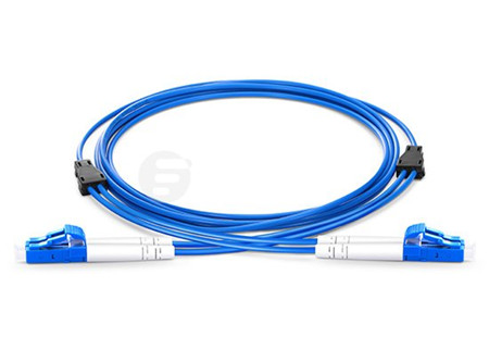
Various types of these light-steel armored fiber cables are in stock in FS.COM, including pre-terminated armored fiber patch cables, armored fiber trunk cables and field-terminated armored fiber cables for both indoor and outdoor applications.
Features:
- Provides excellent crush resistance for outdoor direct burial cables
- Protects cables from rodent biting
- Decreases water ingress into the fiber which prolongs the fiber cable’s life expectancy
Central Strength Member
Strength member is used to increase the tensile force that will be applied on the cable during installation. Strength member will take the pulling force and will keep the fibers safe during installation. For large fiber count cables, a central strength member is often used.
The central strength member provides strength and support to the cable. During fiber optic cable installation, pulling eyes should always be attached to the central strength member and never to the fibers. On fiber splice enclosure and patch panel installations, the cable central strength member should be attached to the strength member anchor on the enclosure or patch panel.
Conclusion
When you choose to use which type of the fiber optic cables, the fiber optic cable construction, along with the mechanical and environment requirements should all be taken into account. All the above materials in the fiber optic cable construction are specifically required to meet the network infrastructure. FS.COM fiber optic cables come in various types with detailed specifications displayed for your convenient. These quality cables are designed with best-in-class performance. For more information about fiber optic cables or patch cords, you can visit fs.com.
Posted by: fernxu123 at
03:09 AM
| No Comments
| Add Comment
Post contains 775 words, total size 8 kb.
October 20, 2016
Per-terminated cabling is a popular type of termination method that has been used by the overall network designers. It provides an plug-and-play solution for links between switches, servers, patch panels, and zone distribution areas in the data center. Compared to the Fusion splicing, pre-terminated cabling is apparently more suitable to meet the high-bandwidth, high-density network needs. An article entitled "Understanding Pre-Terminated Cabling and Network Deployment†offers some detailed information about the pre-terminated cabling and its advantages. This article will go further to talk about the elements of the pre-terminated cabling including the pre-terminated trunk cables, and plug and play cassettes.
Pre-terminated Trunk Cables
Pre-terminated trunking cable assemblies provide an easily installed and cost effective alternative to individual field-terminated channels. There are basically pre-terminated fiber cabling and pre-terminated copper cabling, which will be ntroduced in the following part.
- Pre-terminated MTP/MPO Trunk Cables
Pre-terminated trunk cable usually terminated with MTP/MPO connectors on both ends that provides a quick-to-deploy, scalable solution that improves reliability and reduces installation time and cost. They are capable of supporting multiple users or devices from one point to another while distributing multiple data channels, which is a convenient and economical alternative to running multiple jumpers or fiber cables. Generally 12-fiber MTP/MPO trunk cables and 24-fiber MTP/MPO trunk cables are commonly used separately for 40G applications and 100G applications. The following picture is a 72-fiber female to female MTP trunk cable.
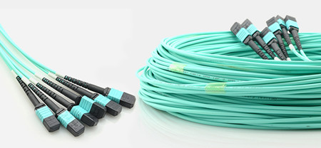
There are also high fiber count MTP/MPO trunk cables which have several legs on both ends. The following picture shows a 72-fiber MTP/MPO trunk cable. There are 6 legs on both ends with each leg terminated with a 12-fiber MTP/MPO connectors.
- Pre-terminated Copper Trunk Cables
Pre-terminated copper cable assemblies including pre-terminated copper trunks and copper patch cords (usually terminated with RJ45 connector), are ideal solutions for data center applications where requires high-efficient deployment. Pre-terminated copper trunk cables are commonly used in point-to-point connections in data centers, such as achieving reliable connectivity between server and switch cabinets. It is a bundle of category cables, built with a choice of 6, 12, or 24 cable bundle and factory terminated with jacks and plugs. The following image shows a jach-to-jack pre-terminated copper trunk cable.
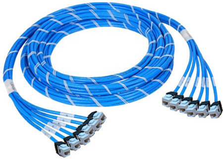
With factory pre-terminated and tested parts, the pre-terminated copper cable assemblies can help users save time and reduce waste. In addition, they allow fast and easy installation with reduced labor costs in large copper infrastructures with high-density cross-connection and patching systems. FS.COM’s pre-terminated copper cable assemblies are pre-bundled and pre-labeled styles, available in Cat 5e, Cat 6 and Cat 6a UTP and STP cable constructions in jack to jack, plug to plug and jack to plug termination ends.
Pre-terminated MTP Cassette—No Work, No Tools, No Mess
MTP cassettes are used to break out the 12-fiber MTP connectors terminated on trunk cables into simplex or duplex-style connectors. Simplex and duplex style jumpers can then be used to patch into transceiver terminal equipment ports, patch panels or client ports. The cassette features simplex or duplex port adapters across the front and one or two MTP connector adapters across the back. A factory-installed and tested optical fiber assembly inside the module connects the front adapters to the back MTP connector adapter. Alignment pins are pre-installed in the MTP connector located inside the cassette. The below image shows the 12-fiber and 24-fiber MTP cassette.
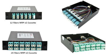
Using MTP cassettes provides adaptability for the changing data center environment. Facing technology refresh frequencies of 12-18 months, Plug & Play MTP cassettes used in the data center offer a great advantage. When connector requirements change in the future, simply swap the cassettes whilst leaving the existing backbone infrastructure intact. 12-fiber MTP to LC and 24-fiber MTP to LC cassettes provide a quick and efficient way to deploy up to 12 LC or 24 LC fiber ports in a single module respectively. MTP to LC cassettes are a quick and efficient way of deploying MTP connector breakout. These cassettes provide significant installation savings with no field terminations required. Simply plug-and-play!
Conclusion
Pre-terminated cabling is the perfect solution to achieve simple and quick installation. Additionally, the transmission testing of pre-terminated cable assemblies is performed by the manufacturer before shipment, and test reports are included with the assemblies. FS.COM offers a full range of high-quality but low-price pre-terminated cable assemblies. Besides that, we also offer Fiber Taps, J-Hook, Fiber Optic Enclosures, Cable Ties, Fiber Optic Wall Plates, etc. And all of them are tested before shipment. If you have any requirement, please send your request to us.
Posted by: fernxu123 at
04:06 AM
| No Comments
| Add Comment
Post contains 755 words, total size 7 kb.
October 18, 2016
With the emerging high-speed network standards and rapidly advancing technology, fiber optic network is driven to meet the growing demand for faster access to larger volumes of data. Although 10G/40G Ethernet becomes the mainstream of telecommunication market nowadays, organizations of all sizes still need to be prepared to integrate speeds of 100G and beyond. For data center networking, users can choose different solutions based on the different transmission distance need. In general, there are two kinds of 100G fiber optic solutions: direct cabling and breakout cabling. It is essential for users to understand the detailed information of each type of solution in order to select the one that meets their current and future connectivity needs.
How 100G Optics Develop
After the IEEE completing the certification of the first 100G standard for Ethernet networks, the transceiver industry launched a new type of form factors for 100G connectivity—CFP ("C" for 100, and FP for Form factor Pluggable). Compared to the most popular 40G QSFP, the size of CFP transceiver is huge. And most CFP implementations doubled the power consumption per bit. Furthermore, the price per bit increased by a factor of ten. These disadvantages becomes the main obstacles of the popularity of 100G CFP transceivers.
The next version of 100G form factors is the CFP2, CFP4, and the CPAK that are improved upon the CFP. But when compared to the popular 10G SFP+ and 40G QSFP+, none of these new members of the CFP family improved density, power consumption, or cost. Fugure 1 shows the size comparison between CFP2, CFP4 and QSFP28 modules.
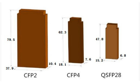
Then here came the 100G QSFP28. The QSFP28 is the exact same footprint as the 40G QSFP+. The 100G QSFP28 is implemented with four 25-Gbps lanes, Just as the 40G QSFP+ is implemented using four 10-Gbps lanes. In all QSFP versions, both the electrical lanes and the optical lanes operate at the same speed, eliminating the costly gearbox found in CFP, CFP2, and the CPAK. The 100G QSFP28 makes it as easy to deploy 100G networks as 10G networks. When compared to any of the other alternatives, 100G QSFP28 increases density and decreases power and price per bit. That’s why it is fast becoming the universal data center form factor. The following part will move on to talk about the 100G optic cabling solutions.
100G Direct Cabling Solutions
QSFP28 transceiver utilizes either fiber or copper media to achieve 100GbE communication in each direction. This transceiver has 4 individual 25GbE lanes which can be used together to achieve 100GbE throughput or separately as 4 individual 25GbE connections (using 4 SFP28 modules).
For 100G short-reach direct cabling within 100m, 100GBASE-SR4 QSFP28 optical module and 100G QSFP28 cable are good choice. Just from the table list of FS.COM 100G optical modules and cables, we know that 100GBASE-SR4 QSFP28 modules can support up to 100 m on OM4 12 fiber multimode MTP cable. And 100G QSFP28 to QSFP28 direct attach copper cable can support up to 5m and 100G QSFP28 to QSFP28 active optical cable can support up to 10m. Figure 2 describes a 100G direct cabling with the use of QSFP28 to QSFP28 DAC and AOC cables.
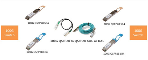
For 100G long-haul direct cabling, like 10km, both 100GBASE-LR4 QSFP28 optical module and 100GBASE-LR4 CFP4 transceiver can support up to 10km on single-mode LC patch cables. For longer 100G direct cabling above 10km, the 100GBASE-ER4 CFP is the ideal choice as their transmission distances support up to 40 km.
100G Breakout Cabling Solutions
A breakout cable is a multi-strand cable, typically custom-made, which is divided into multiple duplex cables. For instance, a 40G breakout cable has four individual 10G duplex cables totaling eight strands, while a 100G breakout cable has 10 duplex cables and 20 strands. Figure 3 displays a simple 100G connectivity with 100GBASE-SR4 QSFP28 and QSFP28 to 4SFP28 breakout cables.
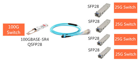
Between the 100G optical module and 25G optical modules, there always uses the breakout cables connected the two kinds of optical modules, and the common cable solutions are 100G QSFP28 to 4SFP28 Breakout AOC cables or 100G QSFP28 to 4x 25G SFP28 Breakout Direct Attach Passive Copper Cables.
The commonly used 100G breakout cabling solutions is 100G QSFP28 to 4SFP28 DAC. It’s easy to understand how this type of cable function. Just as the QSFP+ breakout cable, the 40GBASE-SR4 QSFP+ optical module at the one end can be connected to 4x10GBASE-SR SFP+ optical modules at the other end.
Conclusion
As IT infrastructures are planning to migrate to 100G data rate, network designers must carefully weigh alternative implementations of such links. With a variety of fibers already deployed, it is important to understand the interoperability of new optics with existing fibers. And for 100G deployment, you are supposed to understand the benefits and challenges of each type of the fiber optic solutions before taking an action. FS.COM’s 100G FHD series covers a full range of 100G optical transceivers and cables, like CFP, CFP2, CFP4, QSFP28, as well as 100G QSFP28 to QSFP28 DAC, 100G QSFP28 to 4SFP28 DAC. Besides the above products, 100G FHD Fiber Enclosures, 100G FHD MTP Modular Cassettes, 100G 160 Fiber 2U Panels and 100G CFP SR10 Cables are also provided. If you want to know more about our products, please contact us directly.
Posted by: fernxu123 at
02:52 AM
| No Comments
| Add Comment
Post contains 879 words, total size 7 kb.
October 14, 2016
Due to the server consolidation, virtualization, and performance improvements, data center designers are eager to migrate from 10G to 40G to better meet their network demand. However, there are many 40G optical transceivers and cabling solutions available for sale, such as QSFP-40G-SR4, QSFP-40G-LR4, QFX-QSFP-40G-ESR4, as well as QSFP DAC/AOC cables. So, which one is the most cost-effective solution? No one can give you an exact answer without the detailed information. The above 40G optical transceivers and cables have already been introduced in the previous articles. Today, I am about to shed light on a new QSFP optical transceiver—SMF&MMF 40G QSFP+ (QSFP-40G-UNIV) and its function in 40G migration.
What Is SMF&MMF 40G QSFP+ Transceiver?
The typical fiber optic transceiver may either operate on multimode fiber or single-mode fiber. For example, the Cisco QSFP-40G-SR4, QSFP-40G-LR4 can only operate over multimode fiber for up to 150m, and single-mode fibers with a link length of 10km, respectively. However, a SMF&MMF 40G QSFP+ transceiver as the name implies, can be used with both multimode and single-mode fibers without the need for any software/hardware changes to the transceiver module or any additional hardware in the network. This is usually accomplished (seen in Figure 1) by combining four 10G optical channels at different wavelengths (1270, 1290, 1310, and 1330 nm) inside the transceiver module to transmit and receive an aggregate 40G signal over a single pair of multimode or single-mode fibers.

40GBASE-UNIV and 40GBASE-LX4 QSFP+ Transceiver Overview
Vendors like Huawei, Arista, H3C and Cisco all offer QSFP-40G-UNIV optical transceivers. Based on IEEE 40GBASE-LR4 specifications, QSFP-40G-UNIV operates in the 1310nm band. It uses a duplex LC connector and supports distances up to 150 m over OM3 or OM4 multimode fiber and up to 500 m over single-mode fiber (different vendor may have different specifications). Besides the QSFP-40G-UNIV transceivers, 40GBASE-LX4 QSFP+ transceiver is the other type of the SMF&MMF 40G QSFP+. Take Juniper JNP-QSFP-40G-LX4 as an example, the Juniper 40 Gbps LM4 QSFP+ optical transceiver, part of the Juniper family of optical transceivers, is optimized to fully leverage 40 Gigabit Ethernet (GbE) switches and routers. Figure 2 shows FS.COM SMF&MMF 40G QSFP+ transceiver solutions.
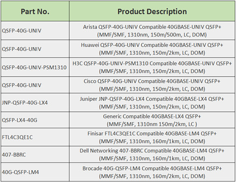
Why Should We Use SMF&MMF 40G QSFP+ Transceiver to Achieve 40G Migration?
With the increase in data center bandwidth requirements, migration to 40G for switch to switch connections is in higher demand. SMF&MMF 40G QSFP+ transceiver is designed to allow for seamless migrations from existing 10G to 40GbE networking without requiring a redesign or expansion of the fiber network. Besides, this transceiver also provides a cost-effective solution to migrate from multimode to single-mode fiber, allows a single-mode fiber infrastructure for distances up to 500m. The following part presents the unique merits of SMF&MMF 40G QSFP+ transceiver.
- Upgrade to 40G Without Additional Cables
The existing QSFP+ transceiver like QSFP+ SR4, QSFP+ CSR4 and QSFP+ LR4 optics, utilizes four independent 10G transmitters and receivers for an aggregate of 8 cables for 40G links. Therefore, customers have to add additional fiber to increase the number of 40G links. However, a SMF&MMF QSFP+ uses duplex LC connector that is consistent with the existing 10G connections, which are also commonly MMF cables with duplex LC connectors. Therefore, a SMF&MMF QSFP+ allows the same cables to be used for direct 10G connections to direct 40G connections, resulting in zero-cost cabling migration. What’s more, by deploying the SMF&MMF 40G QSFP+ transceiver, customers increase the number of 40G links by 4 times without making any changes to their fiber infrastructure, which greatly expand network scale and performance. Figure 3 shows the difference between QSFP+ SR4 QSFP+ and 40GBASE-UNIV universal modules.
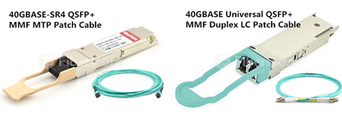
- Realize the Migration From Multimode to Single-mode Fiber
There is a increasing trend for data center designers to move to single-mode optical solutions due to the distance limitations of the multimode cabling system. When data rates increase from 40G to 100G and beyond to 400G, it is just not that easy to move to single-mode cable system for cost effectiveness. Because network managers needs to replace all the old multimode optical devices into brand new single-mode equipment, which usually costs a large mount of money. However, with SMF&MMF QSFP+ optic module, migrating to 40G and 100G will be simpler. As SMF&MMF QSFP+ interoperates with 10km QSFP-LR4 optics, it s a cost effective solution for SM fiber infrastructure for distances up to 500 m.
- Simplify the 40G Cabling System
The SMF&MMF 40G QSFP+ transceiver offers the unique advantage of operating on both multimode and single-mode fiber without any requirement for additional hardware or software. Customers can consolidate their optics and use SMF&MMF QSFP + in their network irrespective of the fiber type, which makes full use of the existing cabling systems, reduces the cost of deployment and of support, and simplify purchasing and deployments.
Conclusion
SMF&MMF 40G QSFP+ transceiver offers a cost-effective transition path for migrations to single-mode fiber in data centers with a single transceiver that bridges the gap between multimode and single-mode optics, enabling data centers running at 10G today to seamlessly upgrade to 40G without having to re-design or modify the cable infrastructure. FS.COM offers a full range of 40G optical transceivers and cables that ensure the smooth migration to 40G data center deployments. Products like QSFP-40G-SR4, QSFP-40G-LR4, QFX-QSFP-40G-ESR4, as well as QSFP DAC/AOC cables are well-tested and fully compatible with major brand. The SMF&MMF 40G QSFP+ transceivers are also offered with very competitive price but high quality. Contact us if you are interested.
Posted by: fernxu123 at
06:35 AM
| No Comments
| Add Comment
Post contains 912 words, total size 8 kb.
October 13, 2016
Without denying that the market for 100G data center optics is accelerating, and more and more telecommunication vendors are aiming to seize this opportunity to launch cost-effective 100G solutions. FS.COM also offers a series of 100G optical modules and cabling solutions that are compliant to the IEEE standards. Our 100G optical modules support different transmission distance from 100m, 10km and more reach options in CFP and QSFP28 form factors. Before introducing the FS.COM 100G optical modules, let’s firstly talk about the 100 Gigabit Ethernet standard.
IEEE 100GbE Standard Introduction
Defined by the IEEE 802.3ba-2010 standard, 100 Gigabit Ethernet (100GbE) technology was given birth to transmit Ethernet frames at the rates of 100 gigabits per second. The 100G optical modules are not standardized by any official standards body but are in multi-source agreements (MSAs). The major 100Gigabit Ethernet 100GBASE-R optical module standards are briefly listed in the below table.
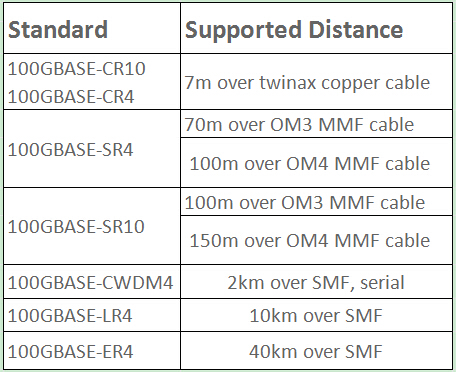
According to the above table, the 100GBASE-CR4 and 100GBASE-CR10 standards were met by twinax copper cable with a link length of 7m. The 802.3bm standard was approved in 2015, which specifies a lower-cost optical 100GBASE-SR4 PHY for multimode fibers (MMF). The 100GBASE-SR4 standard can operate over OM3 MMF for a link length of 70m, and transmit over OM4 for a link length of 100m. QSFP28-100G-SR4 is one of the common types of the 100G modules, which can be used in 100 Gigabit Ethernet links on up to 100m of OM4 multimode fiber.
For those infrastructure who require a link length longer than 2 km, 100GBASE-LR4 and 100GBASE-ER4 standards were introduced. These two standards are specially designed for use in long haul applications. For example, QSFP28 100GBASE-LR4 optics can support a distance of 10km, and the CFP 100GBASE-ER4 operate over single-mode fiber for a distance of 40km.
As for the 100GBASE-SR10 or 100GBASE-CR10, the 10x10 MSA was intended as a lower cost alternative to 100GBASE-SR4 for applications, which defines an optical Physical Medium Dependent (PMD) sublayer and establish compatible sources of low-cost, low-power, pluggable optical transceivers based on 10 optical lanes at 10 Gbit/s each.
FS.COM 100G Optical Modules
FS.COM provides 100G QSFP28 optical modules, including 100G QSFP28 SR4, 100G QSFP28 LR4 as well as 100G CFP LR4 optical module. All these 100G transceivers are good choice for today’s high-density data center 100G interconnection and networking.
- QSFP28 100GBASE-SR4
The QSFP28 100GBASE-SR4 transceiver, based on the QSFP28 from factors, is a parallel 100G optical module designed with optical/electrical connection and digital diagnostic interface. It offers 4 independent transmit and receive channels, each capable of 25Gbps operation for an aggregated data rate of 100Gbps for 100 m on 12-fiber MPO/MTP OM4 multimode fiber.
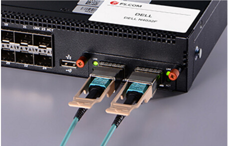
The QSFP28 SR4 module is a vertically integrated solution that meets IEEE 802.3 standards and MSA requirements with power dissipation well under 3.5W. It supports both 100GBASE-SR4 as well as 4x25G breakout applications, 100G QSFP28 to QSFP28 DAC and 100G QSFP28 SR4 to 4x25G SFP28 break-out cables, meeting the harshest external operating conditions including temperature, humidity and EMI interference.
- QSFP28 100GBASE-LR4
The 100GBASE-LR4 QSFP28 transceiver, compliant to 100GBASE-LR4 of the IEEE P802.3ba standard, is also a 100Gbps transceiver module designed for long-reach communication applications. This module converts 4 input channels of 25Gbps electrical data to 4 channels of LAN WDM optical signals and then multiplexes them into a single channel for 100Gbps optical transmission. The high performance cooled LAN WDM EA-DFB transmitters and high sensitivity PIN receivers provide superior performance for 100GbE applications up to 10km links over single-mode fibers.
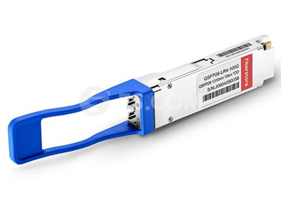
Conclusion
According to the market researchers, the 100G optical transceivers market will be booming in the near future. So what are you waiting for? It is the ideal time for data center designers to prepare for the data center networking and architecture beforehand with 100G transceivers and cables. Contact us for the available 100G optical modules: 100G QSFP28 SR4, 100G QSFP28 LR4, 100G CFP, CFP2 and 100G CFP4 optics. Besides 100G optical modules, FS.COM also provides 100G cable solutions like 100G active optical cable (AOC) and 100G direct attach cable (DAC). You can have what you need here.
Posted by: fernxu123 at
03:16 AM
| No Comments
| Add Comment
Post contains 683 words, total size 6 kb.
October 11, 2016
The present 10G network infrastructure has absolutely no more capacity from which we can grow. They just need to scale it up by using 40-Gigabit Ethernet QSFP+ equipped devices and with further scalability options in the near future. But most people may run into an awkward situation that they are out of money to upgrade all of the 10G hardware. Thus owing to the price perspective, some users still stay at 10G Ethernet network. QSFP+ to SFP+ cables or QSFP+ to 4SFP+ fanout cables are introduced to offer a highly cost-effective way to establish a 40G links, which is sure to be a great news to them. QSFP+ to SFP+ direct attached cables (DAC), as an essential component to support 40G connectivity, will be introduced in this passage.
QSFP+ Cables
Despite the fact that there are several QSFP+ cables available for sale, the optical QSFP+ DAC cables are sure to be the best of them. In general, QSFP+ DAC cables are marked as the most cost-effective cables used inside a short distance for 40G data center connectivity. This cables are exceptionally flexible and utilize the QSFP+ connector to compose the most of signal’s potency.
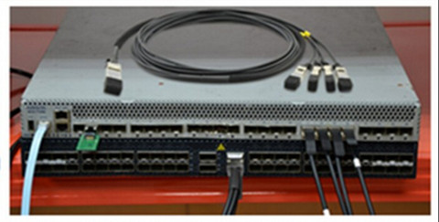
Compared with the fiber optic cables, this cable features firmness and thickness, which make up its sturdiness and reliability. The QSFP+ to SFP+ cables are supposed to be factory terminated in order to meet up the discrete specifications so that it can be ordered to the length. Another feature of the cable which makes it idiosyncratic is its robustness. The cables are made up of leading edge technology and try to allow you to cherish your internet for long hours. There are basically two types of QSFP+ DAC cables: QSFP+ to QSFP+ cables, QSFP+ to SFP+ cables. The following part will continue to talk about the QSFP+ to SFP+ cables.
QSFP+ to SFP+ Cables
QSFP+ to SFP+ cables connect a single 40G QSFP+ port of a QSFP+ switch on one end and four SFP+ ports of s SFP+ on the other end, allowing users to connect multiple ports of SFP+ equipment to QSFP+ based equipment with a single, easy-to-manage assembly just as seen in the below image. The QSFP+ to SFP+ hybrid assembly's four hot-pluggable SFP+ connectors are factory-terminated to twinaxial shielded cable to provide superior signal integrity in support higher frequency data rates. The assemblies are impedance matched to ensure interoperability with SFP+ host ports and minimize insertion loss.
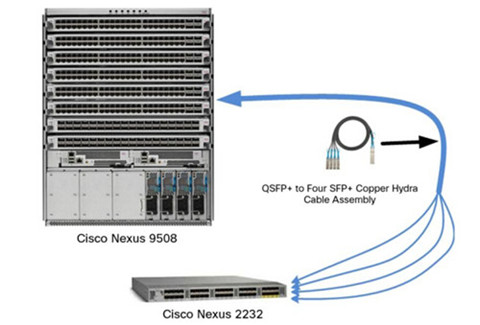
The four 10G SFP+ connectors feed into a single 40Gb/s capable QSFP+ connector. The 4-lane QSFP+ form factor interface supports up to 10Gb/s per lane, providing 40G data transfer rates. In terms of both physical connector space and data throughput, a single QSFP+ connector can replace up to four standard SFP+ connections, providing greater port density and reduced system cost.
Designed for link lengths up to 5 m, these low-power interconnects are compatible with a wide array of data protocols, including InfiniBand 4X SDR, DDR, QDR as well as Ethernet 10G, 40G (IEEE-802.3ba) and SONET electrical failover 40G links. They also support Fibre Channel SAN 10G, 40G and SAN; RapidIO and Myrinet 40G systems links.
Summary
Maybe it is the ideal time for you to cost-effectively upgrade from your older, slower 10G networks to the newer, faster 40G optical network by using the 40G copper cables. QSFP+ DAC cables, especially the QSFP+ to SFP+ cables, will be sure to offer you a remarkable and hassle free experience. If you have made up your mind to embrace a brand new internet speed, FS.COM’s QSFP+ and SFP+ interconnects is automated, and walk through the testing challenges and 100% compatibility.
Our QSFP+ to SFP+ hybrid cable assemblies were developed as a cost-effective means of integrating higher performance QSFP+ equipment with current SFP+ systems in high-performance computing, enterprise networking, video networking and network storage applications. Each end of the hybrid assembly is compliant to the SFF specifications that define the mechanical and electrical requirements for interoperability. If you have any requirement of our products, please send your request to us.
Posted by: fernxu123 at
02:55 AM
| No Comments
| Add Comment
Post contains 676 words, total size 5 kb.
August 08, 2016
Almost every user encounters the similar problem: the Internet is not fast enough. The slow response to net surfing isn’t just browser latency, but also about the network interconnections themselves. To put it simply, increased viewing of TV and downloading of videos further burdens the Internet. Despite some bandwidth-hunger applications are faster than ever, the carrier backhaul networks slow everything down. On top of that, the cloud computing applications require considerably faster networks. Coming to this solution are fiber optic networks.
In each fiber optic network, a fiber optic transceiver and an optical fiber constitute the fiber optic data link. The transceiver is designed to operate over specific fiber cable type. For instance, SFP-10G-SR, a Cisco compatible 10GBASE-SR SFP+, is manufactured to work on multi-mode fiber (MMF). Optical fiber has been adopted in many high-performance optical networks. In a word, fiber optics offers other benefits besides simple speed. These benefits do, however, require expertise in the design of fiber optic cable in order to prevent difficult-to-diagnose failures.
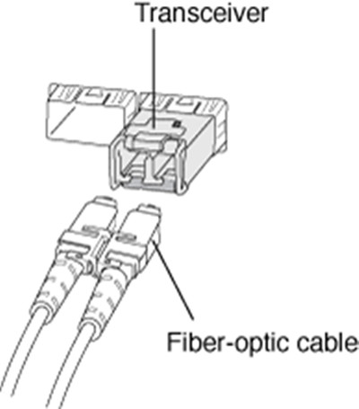
Just mentioned above, fiber optics boasts of many advantages, some of which pack a significant punch in aerospace and defense applications. Actually, airborne applications were among the first to adopt fiber-optic-based design. In such an environment, weight, reliability, and immunity from electromagnetic interference (EMI) are critical concerns. And given the use of airborne platforms in graphics- and processing-intensive Command, Control, Communications, Intelligence, Surveillance, and Reconnaissance (C3ISR) functions, an enclosure must be designed to support extremely high-performance computing.

- Fiber vs. Copper: Cost & Weight
To compare the overall costs of the configuration in the boxes shown above through fiber and Quadrax, a few basic assumptions must first be made. First, for shorter cables, little cost difference exists between optical fiber and Quadrax; however, fiber becomes more expensive for longer runs. Regarding the connectors, while fiber connectors are more expensive than Quadrax, they also support a higher density.
When it comes to the weight savings in the same configuration, though, the reasons to opt for this increased cost become obvious, particularly in airborne and other weight-sensitive applications. While connector weights are roughly the same, the optical cable itself is significantly lighter than Quadrax. Such weight economy also has the added benefit of making optical fiber much less prone to the chafing that arises due to vibration, which can significantly impact Quadrax.
All those explain why fiber-based designs have been so widely adopted in airborne applications ahead of others.
Once it’s decided that fiber optic cable benefits make is applicable for the environment, fiber-specific routing and handling expertise is required to ensure that the resulting system provides the performance, serviceability, and long-term reliability required by applications. Providing strain relief, and minimizing bend radius for optical fiber, are of paramount concern. To understand some basics of handling fiber optic cable, it’s necessary to know about the use of pull-proof connectors with loose-structure cable and non-pull-proof connectors with tight-structure cable, where tight and loose are defined as whether movement is permitted between the outer jacket and the strength member.

Additionally, there are also some other considerations about fiber optic cable bend radius. This is a great concern for this delicate optical fiber since time-to-failure decreases precipitously with increasing bend stress. Much of the bend radius can be ameliorated with the addition of service loops, along with a scrupulous adherence to maintaining the fiber bend radius larger than one inch during installation in addition to final dressing and operation.
Fiber bending occurs in more than one way. Both installation and thermal cycling can result in internal stresses within the cable that create compression "ripplesâ€. In other words, multiple bends may occur within the body of the cable of extremely small radius, which greatly increases the possibility of cable failure.
When a fiber optic cable is seated against the face of a connector, the face of the cable core and cladding will be pushed into the body of the cable by a very small amount, on the order of millimeters, at both ends. Moreover, when a fiber cable is subjected to thermal cycling, swinging back and forth between the extremes of its operating temperatures, this can cause the cable jacket to shrink slightly. In both cases, the result is that the cable core and cladding become compressed within the jacket, and is not free to move in a manner that would relieve the stress. This increases light loss across the fiber and heightens the chance for what’s called a "blocked cable failure†(shown below).

These issues can be addressed via thermal preconditioning, the use of service loops, and limits placed on the restriction of fiber movement. Lastly, the use of an optical backscatter reflectometer can also return useful information about the internal structure of a fiber-optic cable, including very small compression-caused bends within the jacket.
Owing to its speed, weight-saving benefits, fiber optics has been considered as the basic clay of the telecommunications and commercial IT industries. As a professional fiber optic product manufacturer, Fiberstore supplies all kinds of fiber cables with different connectors, like LC fiber cable, MTP cable, SC fiber optic cable, etc.. You can visit Fiberstore for more information about fiber optic cables.
Posted by: fernxu123 at
02:25 AM
| No Comments
| Add Comment
Post contains 878 words, total size 8 kb.
August 04, 2016
When it comes to the topic of fiber optic cables, one word that comes into your mind at first thought usually is speed—the kind of blinding speed needed in high-performance computing for within-box processing as well as between-box communications. Except being somewhat expensive, fiber optic cables have been widely utilized for high-speed connections where their advantages, such as large capacity and long distance, outweigh the cost. Nowadays, the growing higher-speed connectivity requirements are pushing fiber optic technology into more use, typically in servers and long-haul connections. Fiber optics has been adopted as the basic clay of the telecommunications and commercial IT industries, not to mention thousands of miles of high-performance optical networks currently connecting corporations and research institutions around the world.
Just from theory, optical system is simple. There is a light source at one end and a detector at the other. The light goes through the cable and it is not affected by electromagnetic noise like a wired connection. While there is signal loss, it is significantly less than a wired connection, making fiber the preferred method for long distance connections. Laser diodes or LEDs are the usual light source. Lasers include fabry-perot (FP), distributed feedback (DFB), and vertical cavity surface-emitting lasers (VCSEL). Detectors include silicon photodiodes and germanium or InGaAs (indium gallium arsenide) photodetectors.
Fiber optic cable is terminated with the same or different connectors, available in single-mode and multi-mode types, like LC LC multimode patch cord (image below). Often, single-mode fiber (SMF) has a smaller diameter than multi-mode fiber (MMF), and is normally used with a laser source supporting higher bandwidths and longer distances.

In consumer applications, fiber optic cables are usually the case where the connection quality and longer distances offset the cost. The typical connections include high-speed serial interfaces such as USB, Thunderbolt, and PCI Express. Fiber connections are also available for display technologies like DisplayPort and HDMI. In addition, fiber has been used in digital audio applications. S/PDIF (Sony/Philips Digital Interface Format) jacks are common on audio boards and components, including amplifiers and HDTVs.
S/PDIF utilizes a passive fiber optic cable with the emitters and detectors embedded in the devices. Most other fiber-based systems employ an active cable with electronics at both ends.
In the past, fiber optic cables have been widely used in networking, especially in Ethernet. Other networking and storage technologies that support optical connectivity include FibreChannel and InfiniBand. Most of the network adapters and switches embed the transceivers in the hardware or provide a small form-factor pluggable (SFP) interface (image below). (Certainly, there are QSFP+ interfaces to handle 40 Gbit/s.). SFP modules include the optical transceivers and optical connections. Modules can support different passive cable connections including ST, FC, SC, and LC. This allows the cable lengths to be tailored to the installation.

Fiber optic cables use light to carry information. Light has a very high frequency that enables it to carry much more information at any given time. This makes fiber optic cables ideal for applications that use up a lot of bandwidth, like streaming music or video conferencing. Perhaps more importantly, fiber optic cables can carry data much farther than regular copper cables.
Besides, fiber optic cables are made of glass, which means they are not affected by electrical fields. These cables don't need to be grounded because they are not vulnerable to any type of electrical interference that can interrupt or interfere with signals. Fiber optic cables can even be used outdoors because they are immune to atmospheric conditions, including lightning. For those who may be a bit paranoid, another bonus advantage of fiber optic cables is that they can't be tampered with or tapped into as easily as copper wires.
Glass doesn't corrode, meaning that fiber optic cables can endure even the harshest conditions, like outdoors, under soil, or even near chemicals. There's virtually no chance of fire or shock in fiber optic cables because they don't use any electrical energy.
More and more requirements of high-speed connectivity are pushing fiber optic cables in both consumer and enterprise applications, as well as driving multiple fiber connections for building out the cloud to meet the demand for the Internet of Things (IoT). As a professional fiber patch cord manufacturer, Fiberstore provides various kinds of fiber optic cables for high-performance optical networks, LC fiber cable, SC fiber optic cable, ST ST fiber cable all included. You can visit Fiberstore for more detailed information about fiber optic cables.
Posted by: fernxu123 at
03:03 AM
| No Comments
| Add Comment
Post contains 765 words, total size 6 kb.
34 queries taking 0.1089 seconds, 116 records returned.
Powered by Minx 1.1.6c-pink.


