



August 01, 2016
As fiber optic technology develops much maturer, and is widely deployed for private or public applications nowadays, the medium used for signal transmission, fiber optics, or more specifically, fiber optic cable, has become an essential part in fiber optic communications. And in home or business networks, fiber optic installations have seen obvious growth with days passing by. When they are chosen for networks, the installation isn’t a difficult task for installers, especially for those who have the training and qualifications required for the installation job. Generally speaking, in the whole cabling installation process, there are mainly three aspects that call for attention: general cabling guidelines, preparation phrase, and installation process. This text will detail these three aspects respectively.
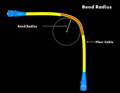
Fiber optic cable is a cluster of glass fibers through which light pulses travel and transmit data at high speeds. Its ends are terminated with the same or different connectors, like LC-SC multimode fiber patch cord whose ends are capped with LC, and SC. Since fiber’s core is glass, the cable needs great attention. It’s ill-advised to crush, stress or overbend fiber optic cable. Every cable has values for minimum bend radius and maximum tensile loading, and it’s unwise to exceed these values. Besides, cables should never be allowed to hang freely for long distances or to press against edges in an installation.
In some cases, some applications may present conditions where the configuration of the equipment will damage the cable by overbending it if precautions are not taken. Conduit bends, pull boxes and joints must be checked to verify that the bend radius is not too small. Innerduct or flexible conduit can be used to ease or sweep the cable around tight corners. The inside radius of conduit bends for fiber optic cable should be at least 10 times the diameter of the cable.
Before installing cables whether for home networking or business, it’s necessary for users to have a written plan and a carefully drawn schematic. Documentation of the design helps users identify any potential problems before they begin their installation. In addition, a design or plan keeps users on track as they move through the strenuous process of installing the cables.
- Component Selection & Cost Estimation
Before installation, it’s imperative for users to estimate the cost of components included in the installation, like the fiber optics cables, the cable ties, the connectors, the closures, the wall jacks, the splices, and so on. For more complex projects, they may need to create a chart listing where each piece of cable or other equipment will be used. Completing a fiber optics installation can be costly, so users should look around for good quality paired with bargain prices.
After the necessary parts are assembled, users should check everything to ensure that there is no damage done to any of the components. The items should be stored in a secure, dry location until the work begins. Since fiber optic cables tend to set in the contour in which they are stored, the cables should be coiled in a figure eight orientation to keep them flexible.
For the entire network installation, it’s no doubt that installing the new cables is potentially the most difficult and complicated part. If the preparation and planning have been carefully executed, the installation may run more smoothly. But users still need a professional on hand to carry out the plan and to provide the necessary hands-on expertise.
- Spare Extra Cable Length
When users work on installation task, it’s a good idea to have plenty of extra cable on hand. Each length of cable should be a few inches longer than the space requires, allowing room for unforeseen obstacles. There should also be some slack so that the cable will not be overstretched.
- Test Components
As users assemble their network, they should test each section of it. This process brings to light any potential problems or incompatibilities before the entire network is in place. If a problem isn’t discovered until after it is assembled, users will have much more difficulty identifying the location of the malfunction. Each component throughout the network should also be tested for compliance to industry standards, and any cables that are being run through a firewall will need to be fire-stopped.
- Pull Cables
An underground channel for fiber optics should be about two inches in diameter. If there is a possibility that additional cables will be added in the future, the conduit should be larger, around four inches in diameter. If the fiber optics cables are being installed in a building, users should avoid bends and opt instead for straight runs through the space within a wall or ceiling.
Cable is typically run or pulled through the space using a rope or a heavy line as a guide. The longer the amount of cable being pulled, the thicker the guide rope should be. The person pulling on the far end should be able to instantly and clearly communicate with the person feeding the cable. It may be necessary to stop the pull to keep from snagging and ruining the cable or to navigate around an obstacle. Some experts suggest using walkie - talkies for communication during this part of the process. A special type of cable lubricant can be used to help the cable slide through the conduit or other space without snagging on objects or corners.

Cables should be labeled on each end. If there are multiple cables running through the same space, they should be secured together with cable ties to maximize space and to minimize tangling.
- Install Cable Protectors
Any cables running across a floor can be a hazard to those walking through the room. In an office or retail location, a loose cord can cause a customer or employee to fall, which may result in a lawsuit that costs the business a significant amount of money. To lessen the hazard factor, users should put cable protectors over any fiber optic cables that have to cross floor space.
Once all the cables are run through the appropriate spaces and all of the closures and wall jacks are in place, the computers and other devices can be hooked up and turned on. If users can access the Internet, they will know that everything has been correctly installed and that their service provider has switched the building to fiber optic service.
It’s easy to find many suppliers and sellers who deal with fiber optic installation components. However, it’s Fiberstore who offers really reasonable prices and fast delivery. Additionly, its products necessary for fiber optic network are all in large numbers of different kinds, such as fiber optic cables, connectors (SC, LC, ST, MTP), compatible fiber optic transceivers (Cisco Linksys MGBSX1, Intel E10GSFPLR, Juniper QFX-QSFP-40G-SR4), etc.. You can try it.
Posted by: fernxu123 at
09:34 AM
| No Comments
| Add Comment
Post contains 1140 words, total size 8 kb.
July 28, 2016
As a communications subsystem, a fiber optic data link connects inputs and outputs (I/O) from electronic subsystems and transmits these signals over fiber optic cables. More specifically, this data link converts an electrical input signal into an optical signal, then sends the optical signal over an optical fiber, and finally converts the optical signal back to an electrical signal, actually operating an alternative to copper cabling or a wireless subsystem. There are three parts included in a fiber optic data link: transmitter, optical fiber, and receiver. And most systems use a transceiver which includes both transmitter and receiver in a single module. This article is intended to introduce some basic information about fiber optic data link, such as its parts, signals and protocols, as well as performance.
A fiber optic transceiver used on each end of a link includes a transmitter and receiver that convert electrical signals to optical signals and vice versa for transmission over optical fiber. The typical data link transmits over two fibers for full duplex links, one fiber in each direction. Some links may allow transmission at several wavelengths of light simultaneously over a single fiber in each direction, called wavelength-division multiplexing (WDM).

The transmitter consists of an interface circuit and a source drive circuit. The transmitter's drive circuit converts the electrical signals to an optical signal by varying the current flow through the light source. The two types of optical sources are light-emitting diodes (LEDs) and laser diodes.
The receiver converts the optical signal exiting the fiber back into an electrical signal. It consists of two parts: the optical detector and the signal-conditioning circuits. An optical detector detects the optical signal. The signal-conditioning circuit conditions the detector output so that the receiver output matches the original input to the transmitter. The receiver should amplify and process the optical signal without introducing noise or signal distortion. Noise is any disturbance that obscures or reduces the quality of the signal. Noise effects and limitations of the signal-conditioning circuits cause the distortion of the receiver's electrical output signal.
Transceivers are designed to work over one specific type of fiber decided by the distance and bandwidth of the communications. For instance, Cisco MGBLX1, a 1000BASE-LX SFP, is dedicated to work over single-mode fiber (SMF) for maximum 10km link length at 1310nm wavelength. HP J4858C, a 1000BASE-SX SFP is designed to operate through multi-mode fiber (MMF) for maximum 550m link length at 850nm wavelength. SMF is used for significantly longer links while MMF for shorter links.
Fiber optic data links may transmit signals that are either analog or digital and of many different, usually standardized, protocols, depending on the communications system(s) it supports. Data links may be protocol transparent, but may also include data encoding to provide more robust data communications. They may be specified by the application or standardized network which they are intended to support, or by the types and bandwidth of signals that they are designed to transmit.
Analog signals are continuously variable signals where the information in the signal is contained in the amplitude of the signal over time. They are the natural form of most data, but are subject to degradation by noise in the transmission system. As an analog signal is attenuated in a cable, the signal to noise ratio becomes worse so the quality of the signal degrades. In contrast, digital signals are sampled at regular time intervals and information is a digital number. They can be transmitted long distances without degradation as the signal is less sensitive to noise.

The power budget is the difference between the output power of the transmitter and the input power requirements of the receiver. The receiver has an operating range determined by the signal-to-noise ratio (S/N) in the receiver. The S/N ratio is generally quoted for analog links while the bit-error-rate (BER) is used for digital links. BER is practically an inverse function of S/N.

The power of the receiver is determined by the output power of the transmitter, and diminished by the loss in the cable plant primarily, but other factors may also affect power budget performance. When the power budget is inadequate for the loss in the cable plant, higher power transmitters or more sensitive receivers or higher bandwidth cable plant are required.
In typical applications, a fiber optic data link serves as a communications medium attached to electronics on either end that provide the other services necessary for communications over the link. Its each part is responsible for the successful transfer of the data signal. As a professional fiber optic product supplier, Fiberstore offers various kinds of fiber optic transceivers e.g. MGBLX1), and optical fibers (e.g. LC fiber cable). You can visit Fiberstore for more information about fiber optic data link products.
Posted by: fernxu123 at
02:32 AM
| Comments (2)
| Add Comment
Post contains 806 words, total size 6 kb.
July 21, 2016
To accommodate the increasing demands for high-speed data transmission and great data capacity, data centers are moving to 40G and 100G transmission networks now. It’s known that 40/100G Ethernet implementations over multi-mode fibers (MMFs) use multiple parallel 10G connections that are aggregated. 40G uses four 10G fibers to send and four 10G fibers to receive, while 100G uses ten 10G fibers in each direction. To ensure that fiber systems work smoothly, each fiber must have a transmitter at one end, and a receiver at the other.
For multi-fiber arrays using MPO/MTP connectors, the TIA 568 standard provides three methods for configuring systems to ensure that proper connections are made, Methods A, B & C. Each of these methods handle the transition from a transmit position to a receive position in a slightly different manner. This article mainly discusses MPO/MTP polarity and its components in 40/100GbE transmission, and the rest passages will only mention MTP instead of MPO/MTP for simpleness.
MTP connector: Each MTP connector has a key on one side of the connector body. When the key sits on the bottom, this is called key down. And when the key sits on top, this is referred to as the key up position. In this orientation, each of the fiber holes in the connector is numbered in sequence from left to right. Here refers to these connector holes as positions, or P1, P2, etc.. Each connector is additionally marked with a white dot on the connector body to designate the position 1 side of the connector when it is plugged in.

MTP Adapter: MTP adapter is used to connect two MTP connectors. This adapter on a cassette is simply a holder with keying designed to hold the two facing ends of the MTPs in correct alignment. The following image shows how the two MTPs are held with the adapter.

MTP Cable: MTP trunk cables serve as a permanent link that connects MTP modules to each other. Available with 12, 24, 48 and 72 fibers, these cables are used to facilitate rapid deployment of high density backbone cabling in data centers and other high fiber environments reducing network installation or reconfiguration. A 72-fiber MTP trunk cable can be terminated with 6 MTP connectors which are manufactured specifically for multi-fiber loose tube or ribbon cable.
MTP harness cables are often terminated with a male/female connector on the MTP side and several duplex LC/SC connectors on the other side, providing a transition from MMFs to individual fibers or duplex connectors. This kind of cable assembly provides a reliable, cost-effective cabling system for migrating from legacy 10G to higher speed 40G/100GbE. For instance, 12-fiber MTP to 4 duplex LC can be used to connect four 10 gig SFP (SFP-10G-SR) with one 40G QSFP+ module (40G-QSFP-SR4).
MTP Cassette Modules: These modules permit rapid deployment of high density data center infrastructure as well as improved troubleshooting and reconfiguration during moves, adds and changes. They enable users to take the fibers brought by a trunk cable and distribute them to a duplex cable. As already assembled units, the MTP cassette modules are fitted with 12 or 24 fibers and have LC, or SC adapters on the front side and MTP at the rear, this is to say, inside a standard LGX cassette module, there is a hydra cable.
Method A, Method B and Method C are the defined methods by TIA 568 standard for proper polarity. To understand these methods, MTP truck cables are used as the object.
Method A: For this method, the transmitâ€receive flip must happen in the patch cords, and the trunk cable is a straight through transmission, with the key up on one end, and the key down on the opposite end(image below).

Method B: This method uses key up connector on both ends of the cable. This type of array mating results in an inversion, which means the fiber positions are reversed at each end. The fiber at P1 at one end is mated with fiber at P12 at the opposing end.

Method C: This method one key up connector and one key down connector. Each adjacent pair of fibers at one end are flipped at the other end. For example, the fiber at position 1 on one end is shifted to position 2 at the other end of the cable. The fiber at position 2 at one end is shifted to position 1 at the opposite end etc.

For 40G transmission using 12-fiber MTP connectors, it transmits 40G using four parallel 10G lanes in each direction. More specifically, there are eight lanes within twelve total positions being employed for transmitting and receiving signals. The four leftmost positions are used to transmit, and the four rightmost positions are used to receive, leaving the four in the center are unused.

For 100G transmission, there are multiple configurations (shown above). However, increasingly it appears that the single port 24-fiber connector is the preferred approach once connector loss is improved.
When it comes to the high networking capacity, it’s no doubt that MTP cable comes as the suitable solution. Select the right polarity method, and then high density and reliability can be achieved. As a professional fiber patch cord manufacturer, Fiberstore supplies various MTP components, including MTP cables, adpaters, connectors, cassettes. You can try here.
Posted by: fernxu123 at
03:08 AM
| No Comments
| Add Comment
Post contains 897 words, total size 8 kb.
July 19, 2016
Copper wires were one the great inventions that let people to power the first telegraphs and telephones, allowing communication over long distances and bringing benefits to people’s daily life. Owing to the advances made in fiber optic technology, coppers are giving way to fiber optics, namely, fiber optic cables, which are used in many applications, from delivering television signals to homes to transferring data between computers that are thousands of miles apart. And when it comes to computer networks, fiber optic cables’ usage is even more obvious.
Installing and maintaining computer networks isn’t tricky, if you follow the step-by-step instructions which will be discussed in details later. Before delving into this topic, let’s first explain some basic information about fiber optic cables.
A fiber optic cable is a cable containing incredibly thin strands of glass or plastic, that can have as few as two strands or as many as several hundred. Its ends are capped with the same or different connectors. Take LC SC cable for example, one side is terminated with LC, and the other side is SC.

Fiber optic cables carry information between two places in the form of light pluses. Light travels down a fiber-optic cable by bouncing repeatedly off the walls. Each tiny photon (particle of light) bounces down the pipe like a bobsleigh going down an ice run. Now you might expect a beam of light, traveling in a clear glass pipe, simply to leak out of the edges. But if light hits glass at a really shallow angle (less than 42 degrees), it reflects back in again—as though the glass were really a mirror. This phenomenon is called total internal reflection. It's one of the things that keeps light inside the pipe.

Although copper has been used in a variety of applications since the 1920s, as it’s inexpensive, easy to use, and a great conductor for electricity. But when compared with fiber optic cable, it’s impossible to deny the great bandwidth capacity even at long distances provided by fiber optic cables. Light has a very high frequency that enables fiber optic cable to carry much more information at any given time. This makes it ideal for applications that use up a lot of bandwidth, like streaming music or video conferencing. Perhaps more importantly, fiber optic cable can carry data much farther than regular copper cables. Besides, fiber optics are also resistant to corrosion, making them a good option for beachfront properties where copper cabling would otherwise be susceptible to degradation by salt and seawater.
To install fiber optic cables on computer networks is not as simple as plugging everything in, but its manageable within people’s abilities.
Firstly, it’s important to choose the right cable type for the computers. There are two main types of fiber optic cables: single-mode fiber (SMF) and multi-mode fiber (MMF). The former is more expensive, but able to transmit 10 gigabits per second up to 37 miles. The latter is used for short distances, up to 1800 feet, able to transfer up to 10 gigabits of data per second. For most office or home networks, the latter is preferable, since there's really no need to cover very long distances.
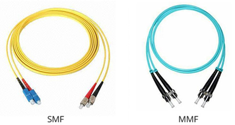
After selecting the right cable type, here goes the detailed installation guide.
Installation Process- Place all the devices in the right position that will be included in the network. The hubs and switches should be placed near the main computer and the wall outlet (for integrated fiber in the loop, IFITL connections). Connect the computer to the wall outlet using the cable and connect the hubs and routers to the computer.
- Add a fiber optic cable to the hub or router and connect it to a second computer to be added to the network. Ensure that there's enough slack in the cable so it's not too tight and easily unplugged. Secure the cables with ties.
- A media converter is necessary for devices that have no fiber optic outlet. This converter changes the light pulses into electricity. Plug this into the computer with a USB or Ethernet cable. Plug in any workstation without a fiber optic outlet into the converter.
- Turn on all the devices and computers on the network.
- Install additional software and drivers on devices if needed.
As for indoor computer networks, most importantly, it’s imperative to make sure that none of the installed fiber optic cables are disconnected or damaged. Cables should be neat and tied together to prevent accidents, and of course, should be kept away from young kids and pets. Fiber optic cables can experience slow or unreliable connections due to excess dust, scratches, or even humidity. An inexpensive laser pointer can help check if the cable is working. Point the laser into one end of the cable and see if the other end lights up. If it does, this means the cable is conducting light properly. If not, the cable will have to be cleaned or replaced.
Fiber optic cables make it possible to send and receive light signals at large amount over long distances. Many applications have replaced copper wires with fiber optic cable, since they allow higher bandwidth and faster speed, resistant to EMI and insensitive to extreme weather conditions. For those who want to buy fiber optic cables, Fiberstore is a good place, available with numerous choices of different types, single-mode (fiber optic patch cables single mode) and multi-mode (LC-SC multimode fiber patch cord). A good site for your cable choice.
Posted by: fernxu123 at
03:06 AM
| No Comments
| Add Comment
Post contains 947 words, total size 7 kb.
July 17, 2016
It’s known that multi-mode (MMF) fiber is available in OM1, OM2, OM3 (e.g. OM3 patch cable) and OM4 versions. How about single-mode fiber (SMF)? There are a variety of SMFs with carefully optimized characteristics available commercially: ITU-T G.652, 653, 654, 655, 656 or 657 compliant. Since several types exist, do you know how to choose a right SMF type to light-up your multi-terabit per second system? The past decades has witnessed the evolution of SMF designs, and most deployed SMFs nowadays are G.652D, G.655 or G.656 compliant fibers. (G.657A is essentially a more expressive version of G.652D, with a superior bending loss performance.) So, in this text, discussion is made on choosing G.652D, G.655 and G.656 compliant fibers against three parameters: attenuation, PMD and CD.
Attenuation is the reduction or loss of optical power as light travels through an optical fiber and is measured in decibels per kilometer (dB/km). G.652D offers respectable attenuation coefficients, when compared with G.655 and G.656. However, It should be remembered that even a meager 0.01dB/km attenuation improvement would reduce a 100km loss budget by a full dB - but let's not quibble. No attenuation coefficients for G.655 and G.656 at 1310? It was not, as you may immediately assume, an oversight. Both G.655 and G.656 are optimized to support long-haul systems and therefore could not care less about running at 1310nm. A cut-off wavelength is the minimum wavelength at which a particular fiber will support SM transmission. At ≤1260nm, G.652D has the lowest cut-off wavelength - with the cut-off wavelengths for G.655 and G.656 sitting at ≤1480nm and≤1450 respectively - which explains why we have no attenuation coefficient for them at 1310nm.

PMD, polarization-mode dispersion, is an unwanted effect caused by asymmetrical properties in an optical fiber that spreads the optical pulse of a signal. Slight asymmetry in an optical fiber causes the polarized modes of the light pulse to travel at marginally different speeds, distorting the signal and is reported in ps / √km, or "ps per root km". Oddly enough, G.652 and co all possess decent-looking PMD coefficients. Now then, popping a 40-Gbps laser onto fiber up against an ultra-low 0.04 ps / √km, the calculator reveals that the PMD coefficient admissible fiber length is 3,900 km and even at 0.1 ps / √km, a distance of 625km is achievable.

PMD is particularly troublesome for both high data-rate-per-channel and high wavelength channel count systems, largely because of its random nature. Fiber manufacturer’s PMD specifications are accurate for the fiber itself, but don’t incorporate PMD incurred as a result of installation, which in many cases can be many orders of magnitude larger. It is hardly surprising that questionable installation practices are likely to cause imperfect fiber symmetry - the obvious implications are incomprehensible data streams and mental anguish. Moreover, PMD unlike chromatic dispersion is also affected by environmental conditions, making it unpredictable and extremely difficult to find ways to undo or offset its effect.
CD is called chromatic dispersion to emphasize its wavelength-dependent nature, and it has nothing to do with the loss of light. This phenomenon occurs because different wavelengths of light travel at different speeds. Thus, when the allowable CD is exceeded - light pulses representing a bit-stream will be rendered illegible. It is expressed in ps/ (nm·km). At 2.5-Gbps CD is not an issue - however, lower data rates are seldom desirable. But at 10-Gbps, it is a big issue and the issue gets even bigger at 40-Gbps.

G.652D’s high CD coefficient is very poor next to the competition. G.655 and G.656, variants of non-zero dispersion-shifted fiber (NZ-DSF), comprehensively address G.652D’s shortcomings. It should be noted that nowadays some optical fiber manufacturers don’t bother with distinguishing between G.655 and G.656 - referring to their offerings as G.655/6 compliant.
It seems that this approach creates more problems than it is likely to solve - by unacceptably amplifying non-linear four-wave mixing and limiting the fiber to single-wavelength operation - in other words, no DWDM. That, in fact, is why CD should not be completely lampooned. Research revealed that the fiber-friendly CD value lies in the range of 6-11 ps/nm·km. Therefore, and particularly for high-capacity transport, the best-suited fiber is one in which dispersion is kept within a tight range, being neither too high nor too low.
After discussion, it’s clear to make the conclusion that only thing that genuinely separates fiber types for high-bit-rate systems is the third parameter: CD. Actually, one of the most important considerations in the fiber selection process is the fact that optical signals may need to be amplified along a route, which will be discussed in other articles.
Different kinds of SMFs have different characteristics. Hope this passage help you obtain a clear understanding of three parameters considered in single-mode fiber selection. As a professional fiber patch cord manufacturer, Fiberstore supplies various kinds of SMFs for long-haul applications, like LC to LC fiber patch cable single mode. Certainly, MMFs can also be found here. You can visit Fiberstore for more information about fiber optic cables.
Posted by: fernxu123 at
02:46 AM
| No Comments
| Add Comment
Post contains 852 words, total size 7 kb.
July 14, 2016
Over the years, data center bandwidth requirements are expanding at double-digit rates, along with the equally urgent push not to compromise the cost-to-performance ratio. To accommodate the needs of web-scale data centers and cloud-based services, efforts have been made by leading cloud and telco providers to define and drive 25Gigabit Ethernet (GbE) technology. As such, the latest Ethernet speed upgrade path would be 10G-25G-100G, or the possible 10G-25G-50G-100G, instead of 10G-40G-100G. The occurrence of 25GbE changes the data center Ethernet landscape of some enterprises and organizations, creating a viable market for high-speed, reasonably-priced connectivity. How much do you know about this 25GbE network? You may have few insights on it. Don’t worry, this article gives an detailed description about it.
25GbE is defined for 100GbE which is implemented as four 25Gbps lanes running on four fiber or copper pairs. 100G optics (e.g. QSFP28 transceivers) have four lasers, each transmitting at 25Gbps. The twisted pair standard was derived from 40GbE standards development. Using 25GbE with QSFP28 transceivers results in a single-lane connection similar to existing 10GbE technology—but it delivers 2.5 times faster performance. It’s a proposed standard for Ethernet connectivity that will benefit cloud and enterprise data center environments, enabling the transmission of Ethernet frames at 25Gbps, and promoting the standardization and improvement of the interfaces for applicable products. The following table provides a summary of key 25GbE interfaces.

One of the main challenges in data centers is the insatiable hunger for more bandwidth. In 2010, the IEEE ratified a 40GbE and 100GbE standard, and launched a new study group to work on a 400GbE standard to keep up with bandwidth demand.
However, for some cloud providers and other large-scale data center operators, the requests are not more than the simple raw capacity. 10GbE is no longer fast enough. For server to top-of-rack network connections to keep up, you would need to double the number of switches in each rack and use 10GbE NICs. This would lead to impractical budget. The 40GbE isn't cost-effective or power-efficient in top-of-rack (ToR) switching for cloud providers and others that operate at a similar scale.
In such a condition, 25GbE was proposed as a standard for Ethernet connectivity, using a single-lane 25Gbps Ethernet link protocol to deliver the best price per performance ratio. In June 2014, the 25GbE Consortium was formed to promote the technology, and subsequently an IEEE 802 workgroup was formed to develop the standard.
Compared with 40GbE solutions, 25GbE technology provides superior switch port density by requiring just one lane (vs. four with 40GbE), along with lower costs and power requirements. Since 40G short-reach QSFP+ interface is constructed from four parallel links. Extending QSFP+ onto fiber requires four parallel 10Gb streams to transport this to the receiving QSFP+ parallel optics. And long-reach QSFP+ interfaces utilize Wave Division Multiplexing (WDM) to transport the four 10Gb streams over a single pair of fiber (image below). The requirement of four lanes significantly reduces switch port density per switching chip and increases the cost of cabling and optics. While the 25GbE standard requires only a single lane, while delivering 2.5 times more throughput compared to current 10GbE solutions, saving the cost compared to 40GbE solutions.

Besides, deploying 25GbE networks enables organizations to significantly reduce the required number of switches and cables, along with the considerations for the reduction of facility costs related to space, power, and cooling compared to 10GbE and 40GbE technology. Fewer physical network components reduce ongoing management and maintenance costs.
Additionally, the 25GbE physical interface specifications support the form factors, including QSFP28 and SFP28. QSFP28 has four lanes and each lanes supports 25Gbps speed. Each lane requires a serializer/deserializer (SerDes) chipset. The proposed 25GbE standard uses the same physical silicon from a single 25Gbit/s lane, which simplifies the process with just minor changes for forward error correction and lane alignment.

25GbE standard helps reduce capital expenditures (CAPEX) and operational expenditures (OPEX) compared to 40GbE, while meeting the necessary I/O bandwidth requirements in data centers. In addition, some blade server chassis solutions today are limited to only two SerDes lanes for their LAN on Motherboard (LOM) networking ports and therefore cannot implement a four-lane 40Gbps interface.
25GbE specification enables network bandwidth to be cost-effectively scaled in support of next-generation server and storage solutions residing in cloud and web-scale data center environments. At present, Fiberstore supplies many 25G solution products, including QSFP28 to 4xSFP28 DAC cables which serve as the alternative solutions to QSFP28 to QSFP28 DAC (QSFP28 cable). With the technology being much maturer, more and more 25G products will be made available to users.
Posted by: fernxu123 at
02:44 AM
| No Comments
| Add Comment
Post contains 780 words, total size 7 kb.
July 12, 2016
When it comes to the information transmission, three ways are usually discussed. For landline telephone, a wire cable is used to carry the sounds from voice into a socket in the wall, where another cable takes it to the local telephone exchange. As to cellphones, information is traveled through invisible radio waves, a technology called wireless. The third way utilizes the fiber optics, which sends information coded in a beam of light down a glass or plastic pipe. Fiber optic cable is made up of incredibly thin strands of glass or plastic known as optical fibers, whose ends are often capped with the same (SC SC) or different connectors (LC SC) to form fiber optic patch cable , or called fiber optic jumper.
Nowadays, fiber optic cable has been praised for their high-performance capacities. But in practical use, it also troubles installers and users. Not only does the fiber installation process need great care and attention, but also the troubleshooting process is a little tricky. Today, this text will discuss some common problems with fiber optic cables and how to troubleshoot these faults.
To diagnose and repair faults quickly and efficiently, it’s necessary to know some common fiber optic cable problems with the possible causes:
- Broken fibers owing to physical stress or excessive bending;
- Signal signal loss because of a contaminated connector or a cable span that’s too long (faulty splices or connectors also lead to excessive signal loss);
- Faulty connection of fiber to the patch panel or in the splice tray;
- Insufficient transmitting power;
It’s known that the fiber break causes a dead connection. But if there occurs intermittent connection, then what causes it? Here are some possible causes. The cable’s attenuation may be too high because of poor quality splices or too many splices. Or connectors are contaminated by such things as dust, fingerprints, scratches, and humidity. Besides, low transmitter strength and bad connections in the wiring closet all bring about intermittent connection.
While working on fixing this fault problem, the first thing to do is to gather information as much as possible, about the problem’s symptoms and possible causes. Then you can start from the following points.
- Information Collection
It’s imperative to know if the PC has been disconnected or has moved recently. If the fiber optic cable has been disconnected from the PC, it could be that the cable was never reconnected, was reconnected incorrectly, or was contaminated during the time that it was disconnected.
Any changes to the PC’s hardware also cause problems, so it’s important to find out whether the PC’s hardware has been upgraded or not. It’s possible that the cable was never disconnected during the hardware upgrade. If so, there’s a chance that the cable could have been overextended when the PC was moved, or the PC could have been accidentally smashed against the back of the desk or the wall, damaging the connector.
In addition, there is a chance that the cable was never damaged or hooked up incorrectly, but rather that the new hardware is preventing the NIC from working correctly. The exact method by which you’d determine whether or not the NIC is having problems varies with your operating system.
Before repairing fiber optic cable problems, it’s also of great importance to keep in mind that fiber cable can be destroyed if stepped on or bent too sharply, or if a chair is rolled over it.

- Fault Testing
After gathering enough information, now goes to problem diagnosis process.
One way is to disconnect both ends of the fiber cable and hold a laser pointer (image left) up to the cable to see if the light comes out the other end. Or if a laser pointer is unavailable, a bright flashlight (image right) works just as well.

- Testing Results
If no light comes through the cable, then the cable is broken and needs to be replaced. If light does come through the cable, it doesn’t necessarily mean that the cable is good; it just means that the fiber inside the cable hasn’t been completely destroyed. However, if the light comes through the cable and the cable run is shorter than a hundred meters, then the cable will often be good enough to use.
Certainly, there exist other diagnostic techniques, like to disconnect the troubled computer from the fiber optic cable and connecting a PC or laptop to the cable. If the good PC is able to function, then the cable is free from the problem. And the problem could lie in the damaged NIC, or a configuration that could be preventing the computer from recognizing the NIC properly.
If you’re familiar with copper wires, then you may discover that fiber optic cable is totally different, and it’s very fragile. When running fiber optic cable for different applications, there is high chance that problems will occur. In this case, understanding what are possible causes and how to deal with them is helpful in solving problems easily. Of course, although problems exist, the fiber optic cables themselves chosen for project should be of high quality. As a professional fiber patch cord manufacturer, Fiberstore supplies many fiber cable types for various applications, test-assured and cost-effective, like SC SC fiber cable. A good place for your cable choice.
Posted by: fernxu123 at
02:50 AM
| No Comments
| Add Comment
Post contains 891 words, total size 7 kb.
July 05, 2016
Data center, which is full of fiber optic cables (such as fiber cable LC to LC), optical modules, and many other optic products, is the brain of a company and the place where the most critical processes are run. Today we are gonna talk about what they contain, and how they are operated.
Although we have mentioned it above that data center is made up of many optics, there is another important point - large-scale computer systems that have been around it for a while. Computers, certainly, require electricity, as well as protection from theft and the accidental or intentional manipulation of hardware. Put simply, one has to safeguard data centers against external influences and provide them with sufficient cooling. After all, there is a lot of powerful hardware sitting in one place.
In addition to these "hard†factors, one must also take into consideration organizational measures, such as periodic backups that ensure operability. As a rule, the more extensive and critical the hardware and software become, the more time and effort are required to provide optimal protection.
For that reason, a data center preferably consists of a well-constructed, sturdy building that houses servers, storage devices, cables (say OM3 patch cable), and a connection to the Internet. In addition, the center also has a large amount of equipment associated with supplying power and cooling, and often automatic fire extinguishing systems. So next, let’s figure out how a data center works according to power supply and cooling these two aspects.

The data center is connected to two separate grid sectors operated by the local utility company. If one sector were to fail, then the second one will ensure that power is still supplied.
In addition, the data center has 13 diesel generators, which are housed in a separate building. Together, they can produce a total of 29 megawatts, an output that is sufficient to cover the data center’s electricity demand in an emergency. The diesel motors are configured for continuous operations and are always in a preheated state so that they can be started up quickly in the event of an incident. It only takes an outage in just one of the external grid sectors to automatically actuate the generators.
Both the local utility company and the diesel generators deliver electricity with a voltage of 20 kilovolts (kV), which is then transformed in the data center to 220 or 380 volts.
Within the data center, block batteries ensure that all operating applications can run for 15 minutes. This backup system makes it possible to provide power from the time a utility company experiences a total blackout to the time that the diesel generators start up.
The uninterruptible power supply (UPS) also ensures that the quality remains constant. It compensates for voltage and frequency fluctuations and thereby effectively protects sensitive computer electronic components and systems.
A redundantly designed power supply system is another feature of the data center. This enables one to perform repairs on one network, for example, without having to turn off servers, databases, or electrical equipment.
Several servers or storage units have multiple, redundant power supply units, which transform the supply voltage from the two grid sectors to the operating voltage. This ensures that a failure of one or two power supply units does not cause any problems.
As we know, the electronic components will generate heat when in operation. In order to keep data center operate smoothly, cooling a data center is essential, and because of the concentrated computing power, the costs to do so are considerable.
As a result, servers are installed in racks, which basically resemble specially standardized shelves. They are laid out so that two rows of racks face each other, thereby creating an aisle from which the front side of the server is accessible. The aisles are covered above and closed off at the ends by doors. Cool air set to a temperature of 24 to 26°C is blown in through holes in the floor, flows through the racks, and dissipates the heat emitted by the servers.
At higher outside temperatures, the air-conditioning systems are cooled with water, made possible by six turbo-cooling units. They are not all used to cool the data center, given that some are used as reserve units. Should a cooling system fail, the time until the backup unit is operational must be covered. To that end, 300,000 liters of ice-cold water (4°C) are available to absorb the heat from the air-conditioning systems during this period.
To top it off, the turbo-cooling units also have to dissipate heat. There are 18 heat exchangers on the data center’s roof for this purpose, which release hot air into the environment.
If outside temperatures is above 26°C, the heat exchangers are sprinkled with water in order to make heat dissipation more effective through evaporative cooling. The large amounts of water consumed in the summer are covered by waterworks allocated to the data center. The municipal water supply system provides a reserve supply in this case and acts as a failsafe.
After reading this article, hope you have an overview of data center. Anyway, data center is so important for an enterprise that it can help us in how we can provide the strongest offering to our customers. In some day, data center may be synonymous with network operations center (NOC), a restricted access area containing automated systems that constantly monitor server activity, Web traffic, and network performance. And we are really looking forward to it!
Posted by: fernxu123 at
03:00 AM
| No Comments
| Add Comment
Post contains 923 words, total size 7 kb.
June 30, 2016
While talking about electrical applications, one may consider the tough copper because of its high conductivity and great tensile strength. But when it comes to telecommunication situations, here comes the fiber optic cable. Instead of braided or bundled metal, hair-thin fiber optic cables are glass or plastic strands, serving as the communication medium to send optical signals. Fiber optic connectors (e.g.. ST, SC, LC, MTP) are often attached to the fibers in a fiber optic cable, like SC fiber optic cable whose ends are capped by SC connectors. Nowadays, fiber optic cables have great use in many applications, and are sure to see even more growth in future. Now question occurs. Since more and more fibers are deployed in fiber optic systems, how to ensure the safety in fiber optic cable installation? This article is gonna to have detailed description about safety issues in installing fiber optic cable.
While installing fiber optic cables, it’s advised to avoid exposure to invisible light radiation carried in the fiber, and to have proper disposal of fiber scraps produced in cable handling and termination. Besides, the hazardous chemicals used in termination, splicing or cleaning must be handled safely. The following passages list the safety issues that should be followed.
- Eye Protection
It’s recommended to wear safety glasses with side shields. Certainly, the safety eyewear should comply with relevant requirements. In addition, after handling fiber optic cables, to wash hands thoroughly and carefully before touching eyes or contact lenses.

In no case should one look directly into the end of any optical fiber unless it is certain that no light is present in the fiber. The light used for signal transmission in fiber optics is generally invisible to the human eye, but may operate at power levels that do harm to the eye. Inspection microscopes can concentrate the light in the fiber and increase the danger. Keep in mind to use an optical power meter to verify that no light is present in the fiber. When using an optical tracer or continuity checker, look at the fiber from an angle at least 12 inches away from the eye to determine if the visible light is present or not.
- Proper Disposal of Fiber Scraps
During the termination and splicing process, the small scraps of bare fiber may occur. In such a case, these scraps must be disposed of properly in a safe container and marked according to local regulations, as it may be considered hazardous waste.

Under no circumstance can fiber scraps be dropped everywhere, like on the floor, since these scraps will stick in carpets or shoes and be carried elsewhere. The right way is to place them in a marked container or stick them to double-sided adhesive tape on the work surface.
After finishing installation, it’s imperative to clean the work area carefully and thoroughly. And it’s ill-advised to use compressed air to clean off the work area. Remember to sweep all scraps into a disposal container. Of course, one should carefully inspect clothing for fiber scraps when finish working with fiber.
It’s known that fiber particles can be harmful if ingested, so don’t eat, drink or smoke near the working area.
Because confined spaces, such as equipment vaults, manholes can contain toxic or explosive gases or insufficient air to sustain life, it’s better to work only in well-ventilated areas. Besides, because materials and chemicals used in installation processes may be hazardous, they must be handled properly. During splicing process, fusion splicers create an electric arc. Thus, one should ensure that no flammable vapors and no liquids are present.
After discussing safety issues wit h fiber optic cable installation, here goes to another issue. Actually, this issue closely related to fiber optic cable is the cleanliness. The small size of fiber optic cables makes them very sensitive to dust and dirt. Thus, in order to achieve the optimized performance, it’s of great importance to maintain the highest standards of cleanliness, including do the following thins: work in clean areas; keep protective dust caps on connectors, mating adapters, patch panels, or test and net- work equipment; don’t touch the ends of the connectors; use lint-free wipes and pure reagent grade isopropyl alcohol to clean connectors. Other solvents can attack adhesives or leave a residue. Cotton swabs or pads may leave threads behind and are not recommended. Surely, the test equipment should be cleaned periodically.
For safe installation, it’s advised to follow those tips mentioned above. Of course, the points listed in this text are not comprehensive, with only several common issues are talked about. (The premise of safe installation is to choose high-quality fiber cables. You can turn to Fiberstore, whose fiber optic cables available in many types are all test and quality assured, like LC to SC fiber patch cable. You can go there and have a look yourself.)
Posted by: fernxu123 at
03:08 AM
| No Comments
| Add Comment
Post contains 818 words, total size 6 kb.
June 28, 2016
It’s a truth that over the past couple of decades, fiber optics technology has grown tremendously, and has completely revolutionized communications. And today’s telecommunication market is surrounded by countless smart and sophisticated fiber optic products, like optical transceiver modules, patch panels, patch cords (e.g. LC LC multimode patch cord), and so on. Compared with copper wiring, fiber optics is more secure and features less electrical interference. It seems that fiber optics has become a part of everyday lives. Until now, the most prominent use of fiber optics today is the Internet, in which the information is sent digitally through fiber optics across the entire world. Certainly, this is just a piece of iceberg. Here goes other more fiber optics applications.
Telecommunication applications using fiber optics are widespread, ranging from global networks to desktop computers. These involve the transmission of voice, data, or video over distances of less than a meter to hundreds of kilometers, using one of a few standard fiber designs in one of several cable designs.
Carriers use optical fiber to carry plain old telephone service (POTS) across their nationwide networks. Local exchange carriers (LECs) use fiber to carry this same service between central office switches at local levels, and sometimes as far as the neighborhood or individual home (fiber to the home [FTTH]).
Optical fiber is also used extensively for transmission of data. Multinational firms need secure, reliable systems to transfer data and financial information between buildings to the desktop terminals or computers and to transfer data around the world.
Due to the use of use of fiber optics, the transportation system has become more integrated and efficient. With the increase in traffic and more demands for efficiency, "smart highways†have begun to adopt fiber into things like automated toll booths, traffic signals, and message signs that are changeable.
Additionally, the fiber optic cables are being utilized in lots of other technical and complicated ways. Take the electric train (image below) for example, fiber optic cable is used as the transmission medium to control the switching of power semiconductors within the converters that create the right frequency and voltage for the electrical drive motors and electrical systems. A little complicated, right? Since the distances traveled to accomplish such conversions can be quite far, fiber optic cable provides a much better solution than copper.

Besides transportation, fiber optics also has heavy use in military nowadays. The military would test the cables rigorously and decided whether they are perfect for use in many of their applications. They offer better performance, more bandwidth, and greater security for their signals - all at a lower cost. They're strong, and more importantly lightweight, and can also be used outdoors in harsh environments. Thus, optical cabling is an excellent choice for the military's retrieval and deployment applications.

In addition, fiber optics has also started to bring benefits to missile launchers and radar systems. In many of their control systems, a single pencil-sized optical fiber can replace miles (and pounds) of copper wiring.
Maybe UAVs and drones sound unfamiliar to you, since they are the fairly new and fast growing applications of fiber optics. Here UAVs stand for Unmanned Aerial Vehicles. With the ability to provide a fast and efficient way to transmit a large amount of data over long distances, fiber is utilized as the main communication conduit between the UAV and ground control. Or more specifically, between ground control and the antenna that controls the UAV, if you were wondering why there weren't any cables trailing behind drones in all the photos and videos you've seen.
Tiny drones have been entirely powered by "laser over fiberâ€, basically using light and optical cables to make it fly. The fiber has the added benefit of being lighter than copper wiring, and non-conductive, meaning it won't short out any power lines the UAV happens to bumble into, and it won't attract pesky lightning strikes, neither.
Apart from what have been discussed above, other applications also include the utilization of fiber optics, such as the decorative lighting for Christmas trees, signs, and art. Showcases displayed in boutiques use optical fibers to illuminate from different angles using a single light source.
Some special fiber optic cables can be used for sensor applications in areas that involve oil-well monitoring and fire or leak detection. The extra bandwidth offered also enables cable television to transmit signals to their subscribers faster and more efficiently. Fiber also shows up in research institutions, colleges and universities, as well as in the aerospace, biomedical, and chemical industries.
Fiber optics really brings a lot of benefits into people’s daily life,and has become an essential part of it. As a professional fiber patch cord manufacturer, Fiberstore supplies many fiber optic products, like the above mentioned optical modules, patch cords (e.g. MTP cable), etc.. For more information about fiber optics, you can visit Fiberstore.
Posted by: fernxu123 at
02:51 AM
| No Comments
| Add Comment
Post contains 824 words, total size 7 kb.
June 23, 2016
In modern telecommunication networks, fiber optical communication has become the major means for data transmission. And in response to the increasing demands for internet protocol (IP)-based services, including voice, video, and data in highly reliable optical communication, smart transceiver modules are designed by integrating electro-optical converters in many forms, like small form-factor pluggable (SFP) and small form-factor pluggable plus (SFP+ or 10 gig SFP). SFP and SFP+ modules are hot-swappable, easy-to-integrate devices which allow fiber optic devices to be added to existing solutions, such as I/O boxes, camera systems or industrial controllers. They offer a convenient and cost effective solution for the adoption of Gigabit Ethernet (GbE), 10GbE and Fibre Channel (FC) in data center, campus, metropolitan area access and ring networks, and storage area networks. In a word, they are widely used in networking architecture. But have you obtained a deep understanding about them?
A transceiver includes both transmitter and receiver in a single module. The transmitter and the receiver of the SFP transceiver function independently for bidirectional communication. The transmitter takes an electrical input and converts it to an optical output from a laser diode or LED. The light from the transmitter is coupled into the fiber with a connector and is transmitted through the fiber optic cable plant. The light from the end of the fiber is coupled to a receiver where a detector converts the light into an electrical signal which is then conditioned properly for use by the receiving equipment.

Compatible with SFP Multi-Source Agreement (MSA) and SFF-8472, SFP modules are able to work through single-mode fibers (SMFs), and multi-mode fibers (MMFs), with the distance reach ranging from less than 550m over MMFs to 70km over SMFs. Take 1000BASE-SX SFPs (eg. MGBSX1) for example, this port type is standardized to operate over MMF for the possible 550m reach. SFP transceivers are also available with a copper cable interface to connect to unshielded twisted pair networking cable. The copper transceivers can be installed into optical SFP slots, enabling an optical Ethernet port (1000BASE-X) to be converted into a copper Ethernet port (1000BASE-T) either in the field or in production.
SFP transceivers are used in optical communications for both telecommunication and data communications applications, which are designed to support SONET/SDH, GbE, FC and other communications standards.
To fit the growing lusts for the transmission capacity and bandwidth, 10GbE products are brought to the market, including SFP+ and XFP, with the former being the most popular 10G transceiver type currently. As the upgraded version of the SFP, SFP+ transceivers are widely used for 10Gbit/s data transmission applications, like data center, enterprise wiring closet, and service provider transport applications.

Designed with higher data rate and new industrial standards, SFP+ has a more compact size with the former 10G X2 and Xenpak transceivers, more suitable for density installations because of its greater ability. 10 gig SFP is ideally suited for datacom and storage area network (SAN/NAS) applications based on the IEEE 802.3ae and Fiber Channel standards, Fiber Channel 10G, 8.5G, 4.25G, 2.125G, 1.0625G, 10G BASE- SW/SR/LR/ER, 1000BASE-SX Ethernet.
SFP+ transceiver electrical interface is compliant to SFI electrical specifications. The transmitter input and receiver output impedance is 100 Ohms differential. Data lines are internally AC coupled. The SFP plus module provides differential termination and reduce differential to common mode conversion for quality signal termination and low EMI. SFI typically operates over 200mm of improved FR4 material or up to about 150mmof standard FR4 with one connector.
Most of the SFP and SFP+ modules are built with digital diagnostic monitoring (DDM) function, or called digital optical monitoring (DOM) function according to the industry standard MSA (Multi-Source Agreement) SFF-8472. This function can provide component monitoring on transceiver applications in details, such as the real-time parameters of the fiber optic transceivers, like optical input/output power, temperature, laser bias current, and transceiver supply voltage, etc. Besides, DDM interface includes a system of alarm and warning flags which alert the host system when particular operating parameters are outside of a factory set normal operating. Thus, DDM interface can also enable the end user with the capabilities of fault isolation and failure prediction.
SFP and SFP+ transceivers, as the instrumental tools in networking architecture, interface a network device motherboard (for a switch, router, media converter or similar device) to a fiber optic or copper networking cable, working as high-speed pluggable solutions. Fiberstore SFP and SFP+ modules are quality-assured and severely checked for compatibility with devices from some major brands in this industry, like Cisco, HP, Generic, and so on. You can go here for such a product.
Posted by: fernxu123 at
02:41 AM
| No Comments
| Add Comment
Post contains 775 words, total size 6 kb.
June 21, 2016
As fiber optic technology develops and more demands are being placed on data transfer, the needs for higher bandwidth and more connections are also growing accordingly, which makes the use of fiber optic patch cables and transceivers even more important in data transmission. As one of the basic component in optical communication, fiber patch cord consists of a fiber optic cable (single-mode or multi-mode) terminated on both ends with single type or hybrid connector, like SC to SC fiber patch cable, LC to LC fiber patch cable single mode, LC-SC multimode fiber patch cord, LC ST patch cable, etc.. Patch cords are used to connect communication equipment to the cable plant or for interconnections, and their performance matters in the whole fiber optic network. As such, the proper testing of patch cords is essential in ensuring their quality, so as to avoid network problem.
Here goes to the first topic: patch cord testing. After terminating the fiber optic cable with connectors, it’s imperative to test both the connectors’ loss and the fiber loss in the cable. On very short cable assemblies (up to 10 meter long), the loss of the connectors will be the only relevant loss, while fiber will cause the overall losses in longer cable assemblies.

- Testing Process
In testing patch cord, what’s required is the 1310nm LED light source for single-mode fiber (SMF) and 850nm for multi-mdoe fiber (MMF), a fiber optic power meter and some reference patch cords. Use one reference patch cord to set a 0dB reference. Connect a to-be-tested patch cord to the reference patch cord with a mating adapter. Connect the power meter to the other end of the patch cord and measure the loss. Since the length of the fiber is short, the loss contribution of the fiber can be ignored.
Because one end of the cable is attached to the power meter, not another cable, only the loss of the one connection is measured between the reference cable and the cable under test, so each connector should be tested individually. Reverse the patch cord you are testing to check the connector on the other end.
If the equipment has different connectors from the patch cords you are testing, you will need hybrid reference cables with connectors compatible with the equipment on one end and the patch cord connector on the other end. You will also need the correct connector adapters for your power meter. Certainly, all reference cables used for testing must have high quality connectors to get reliable test results.
Whether newly-branded patch cords, or used patch cords, they all encounter an issue—cleanliness. All connectors should always have the polished ferrule covered by a "dust cap†to protect the end of the connector ferrule from damage and dirt. Before inserting connectors in mating adapters or active devices, it’s recommended to clean connectors.
Cleaning ProcessMultiple ways are available to clean fiber optic cables and connectors. Here just list a few useful tips.
- Blow the fiber surface with a stream of Clean Dry Air (CDA) as to dislodge larger, loose particles;
- Place 1-3 drops of spectroscopic grade methanol or isopropyl alcohol in the center of a lens tissue;
- Hold the fiber by the connector or cable. Place the wet portion of the lens tissue on the optical surface and slowly drag it across;

- Examine the surface of the fiber under high intensity light using a magnifier, an optical loop, or a video inspection tool. If streaks or contaminants still remain, repeat the process using a fresh lens tissue;
- Immediately install a protective cover over the end of the cable to avoid re-contamination or insert the fiber for immediate use.
Some users buy large bulks of patch cords and store them in boxes until they are needed to be plugged in. Some users hang them on the sides of the equipment racks. That's not how they should be handled. It seems to be a commonplace that fiber patch cords are always subject to poor treatment (just as the image below shows). They are often hung off communications equipment or patch panels stressing the fiber at the back of the connector. When they are too long, they are bundled and hung in large piles on the side of equipment racks. Kinking is always a problem. Ideally, patch cords should be the right length, supported below the connection and carefully placed to prevent stress.

- Handling Tips
It’s ill-advised to bend the fiber patch cords. Bending the cords may cause internal breaks along the fiber resulting in poor performance or instability. Pay attention to the bend radius of the patch cable. Generally, for 1.6mm and 3.0mm cords the minimum un-loaded bend radius is 3.5 cm. In addition, it’s not allowed to pull or stress the patch cords. During the patching process, excessive force can stress fiber patch cables and connectors, thus reducing their performance.
When it comes to fiber patch cord, there are three aspects: testing closely related to quality, cleanliness, and handling. Once they are properly tested, then their quality is assured. If they are handled in right ways, and kept clean, the fiber optic network with high performance is half-succeeded. As fiber patch cord manufacturer, Fiberstore supplies many kinds of patch cords of high quality, available in single/mode and simplex/duplex version, including the above-mentioned LC to LC fiber patch cable single mode, as well as LC-SC multimode fiber patch cord. For more information about fiber optic patch cables, you can visit Fiberstore.
Posted by: fernxu123 at
02:24 AM
| No Comments
| Add Comment
Post contains 927 words, total size 7 kb.
June 16, 2016
Since it started out as a popular local-area network (LAN) technology, Ethernet has developed unceasingly into a networking method for metro-area networks (MANs). While Fibre Channel and InfiniBand have their places, Ethernet still dominates among data centers that interconnect hundreds and even thousands of servers, routers, and switches. With millions of ports, Ethernet proves itself as the most well-known networking technology worldwide, serving as the networking protocol in data centers. This article discusses the numerous connectivity options offered by 10GbE to data centers.
At initial stages, 1GbE technology had great use in LANs, MANs, and data centers. Lately, the rise of cloud computing, coupled with the increased use of unified data/storage connectivity and server virtualization by enterprise data centers, has led to a great desire for ever-higher data-rate links. Then links operating at 10 Gbits/s were made possible.
Just like its prior generations, 10GbE rapidly dominated in the computing networks because of its ubiquity, the ready and familiar management tools, along with the compelling cost structure. To deploy 10GbE links can take on many forms, ranging from optical modules to copper transceivers which are connected to Cat6A unshielded twisted-pair cable. In 2002, the IEEE created several standards for 10GbE connectivity (802.3ae), including
- 10GBASE-SR: operates over multi-mode fiber (MMF) using optical modules with 850nm lasers
- 10GBASE-LR: operates over single-mode fiber (SMF) using optical modules with 1310nm lasers
- 10GBASE-LRM: operates over MMF using optical modules with 1310nm lasers
- 10GBASE-T: operates over Cat6 or Cat6A twisted-pair copper cabling with distance up to 100m
- 10GBASE-KX4: operates over four copper backplane lanes with distance up to 1m
- 10GBASE-KR: operates over a single backplane lane with distance up to 1m
Besides, a non-IEEE standard approach called SFP+ Direct Attach Cable (DAC) has gained in popularity. It uses a passive twin-ax cable assembly that connects directly into an SFP+ module housing. Take Cisco SFP-H10GB-CU1M for example, this product is the 10G SFP+ direct attach twinax cable assembly for 1m length.

Optical transceivers are housed and available in modules specified by multi-source agreements (MSAs) which are created by module manufacturers and equipment OEMs. Over the years, the form factor had evolved from XENPAK to X2 to GBIC to SFP to XFP and to SFP+ modules.

SFP+ optical modules designed for 10GbE applications are full duplex transceivers. In data centers, 10GBASE-SR (short range) modules have emerged as the most popular variant of the optical options. This 10GBASE-SR compliant transceiver uses 850nm lasers over LC fiber cable, incorporating a vertical-cavity surface-emitting laser (VCSEL), which is lower in both cost and power than side-emitting DFB lasers needed for SMF. Over older FDDI-grade 62.5µm MMF, 10GBASE-SR maximum link length is 26m;over 62.5µm OM1 fiber 33m;over 50µm OM2 fiber, 82m; over OM3 fiber, 300m; and over OM4 fiber, 400m.
For 10GbE applications, copper-based solutions generally fall into two categories: distances appropriate to backplanes within a box, and distances associated with connections between boxes.
Both 10GBASE-KX4 and 10GBASE-KR are intended for inter-box backplane connections with distances up to 1m. The major difference between the two is that KX4 operates over four copper lanes, while KR is a serial 10-Gbit/s link operating over one lane.
Another copper solution is the SFP+ DAC link. This kind of cable assembly is ordered in pre-specified lengths and come with attached SFP+ module form-factor connectors.
The other copper -based connectivity option is 10GBase-T, also known as IEEE 802.3an. With 10GBASE-T, 10-Gbit/s communications occur over unshielded twisted-pair cabling. It’s the fourth generation of so-called GBASE-T technologies, which all use RJ45 connectors and unshielded twisted-pair cabling to provide 10- and 100-Mbit/s, and 1- and 10-Gbit/s data transmission. A 10GBASE-T transceiver uses full-duplex transmission with echo cancellation on each of the four twisted pairs available in standard Ethernet cables, transmitting an effective 2.5Gbits/s on each pair. Category 6 or category 6A cabling is typically used with 10GBase-T. Cat6 is specified for distances up to 55meter, whereas Cat6A is specified for up to 100m.
10GBASE-T connectivity, backward-compatible with the existing 1GbE cabling infrastructure, is the most flexible, economical, and user-friendly 10G Ethernet10GbE connectivity option available. Its benefits include the ability to interoperate with legacy slower technologies, the use of ubiquitous and inexpensive cabling and connectors, the flexibility of full structured wiring reach, the ease of Cat6A cabling deployment, and power-saving features. As a result, 10GBASE-T is ideally suited for the rapidly expanding needs of today’s data centers.
10GbE does well in the inter-switch and storage side, creating a convergence between networks designed primarily for voice, and the new data centric networks. Fiberstore, as a professional fiber optic product supplier, supplies various kinds of 10GbE transceivers fully compatible with major brands at really low prices, as well as detailed SFP+ DAC cabling solutions. Here, you can find what you want quickly for your 10GbE applications.
Posted by: fernxu123 at
03:06 AM
| No Comments
| Add Comment
Post contains 812 words, total size 7 kb.
June 14, 2016
The virtualization and cloud computing, combined with the increasing low-latency services, drive data rates to even much higher points. Just like that 1GbE lines are being aggregated into 10GbE lines, the 10GbE lines are also being amounted to higher rates, say 40/100Gbit/s. With the upward climb in traffic among all sectors, carriers are thirsty for a high-rate connectivity solution. In 2010, the IEEE 802.3ba Task Force has ratified the 802.3ba Ethernet standard. IEEE 802.3ba governs 40/100Gb/s operations across backplanes, copper cabling, multi-mode fiber (MMF), and single-mode fiber (SMF), moving networking speeds forward by another order of magnitude. This standard addresses the needs of computing, network aggregation and core networking applications. And the following passages will discusses this approved IEEE 802.3ba standard in great details.
Back to history, each Ethernet standard has incremented the data speed by about 10 years. What make 802.3ba unique is a 40-Gbit/s option that fits many existing applications. It’s a welcome addition to Ethernet, as it continues to scale with the need. Originally a local-area networking (LAN) technology, Ethernet has gone far beyond its roots thanks to a continuous standards effort. The new standard paves the way for the next generation of high-rate server connectivity and core switching. 802.3ba standard was designed to maintain the widely supported Ethernet frame format and the media access controller (MAC), as well as to create new physical layers (PHYs) for 40/100Gbits/s. It supports full-duplex communication, and works with the International Telecommunication Union’s (ITU’s) Optical Transport Network (OTN) for long haul networks.

- 40/100Gbits/s New PHYs
IEEE 802.3ba standard for 40G/100G offers a wide range of different, mostly optical versions. Backplanes, copper, and PHY media are covered, each usually featuring multiple lanes of 10 or 25Gbits/s. When it comes to 40Gbits/s, its PHYs include the SMF for 10km distance, MMF for 100m link length, copper cable and backplane for 1m. For 100Gbits/s, the PHY goals consist of 40km on SMF, 10km on SMF, 100m on OM3 MMF, and 10m on a copper cable.
- 40/100Gbits/s Form-factors
The quad small form-factor pluggable (QSFP) module with four optical ports, is used for 40G over MMF and SMF. And, the CXP module handles 100G over MMF, and offers two sets of 12 optical I/O ports. The CFP module is a 148-pin electrical connector that has 12 optical I/O ports, able to deal with both 40G and 100G transmission. (CFP2, CFP4, and QSFP28 are also for 100G). Based on 802.3ba standard, various related products have been developed to target at 40/100GbE, like Cisco QSFP-40G-SR-BD (image below), a Cisco 40GBASE-SR BD QSFP module for 40Gbps infrastructure over MMF with duplex LC.

- 40/100Gbits/s Multiple Wavelengths
40Gbits/s links use 1270, 1290, 1310, and 1330nm multiple wavelengths. With 64B/66B coding, the signaling rate is 10.3125Gbits/s. And for 100Gbits/s, data is transmitted at 28.78125Gbits/s over 1295, 1300, 1305, and 1310nm wavelengths. All these wavelength-division multiplexed (WDM) formats match up with what the ITU specifies for its long-haul OTN fiber networks.
IEEE 802.3ba helps to eliminate the pressing bandwidth bottlenecks faced by network providers and end users alike, paving the way for future Ethernet speed increase.
IEEE 802.3ba addresses critical challenges facing technology providers today, such as the growing number of applications with demonstrated bandwidth needs far exceeding existing Ethernet capabilities, by providing a larger, more durable bandwidth pipeline. Furthermore, collaboration between the IEEE P802.3ba 40/100GbETask Force and the ITU’s Telecommunication Standardization Sector (ITU-T) Study Group 15 ensures these new Ethernet rates are transportable over OTNs.
IEEE 802.3ba functions as the catalyst that speed up the unlocking innovation across the greater Ethernet ecosystem. It’s expected to trigger further expansion of the 40/100GbE family of technologies by driving new development efforts. It also will provide new aggregation speeds that will drive new 10GbEnetwork deployments.
In addition to providing an increased bandwidth pipeline, IEEE 802.3ba remains compatible with existing IEEE 802.3 installations, preserving significant industry investment in the technology. The standard is also expected to generate concrete benefits, such as lowered operating expense costs and improved energy efficiency, by simplifying complex link aggregation scheme commonly used in today’s network architectures.
With traffic on IP backbone network continuing to grow at a rapid pace, the approved EEE 802.3ba standard reliefs the traffic on it. It’s timing to deploy 40/100GbE to scale the interconnection within and between the ubiquitous warehouse-scale computing infrastructures. Fiebrstore supplies 40/100GbE solutions, including QSFP+ module, 100G optics, 40/100G cables, and so on. You can visit Fiberstorer for more information about 40/100GbE solutions.
Posted by: fernxu123 at
02:39 AM
| No Comments
| Add Comment
Post contains 757 words, total size 6 kb.
June 09, 2016
With each passing day, fiber optics has become increasingly affordable, widely used for high data-rate systems such as FDDI, multimedia, ATM, or any other network that requires the transfer of large, time-consuming data files. As one of the most basic elements consisting of fiber optics in optical networks, fiber patch cord, or fiber optic patch cable and fiber optic jumper, composes of a fiber optic cable capped with a connector on each end. (In this sense, fiber patch cord can be classified by the connector types, like LC fiber cable, SC fiber optic cable, MTP/MPO cable, etc..). Judging from its structure, patch cord seems to be too simple. But actually, it plays a really important role in the overall network performance whose main problems are caused by patch cord performance. Thus, understanding fiber patch cord performance comes as the priority.
In order to have an in-depth understanding of fiber patch cord performance, this text will be spread from two aspects: the perfect patch cord and polishing conditions.
When a patch cord made by a mated pair of connectors has near zero insertion loss and a relative power loss, then it’s called perfect patch cord whose performance should be in accordance with fiber splicing loss that is on the order of 0.02dB. It needs to meet these requirements: insertion loss <0.05dB and return loss >58dB.
- Notices on Making "Perfect Patch Cordâ€
To make a "perfect patch cordâ€, the endface has to be kept clean, meaning that cleanliness of the production line and the cleaning technique are very important. Besides, the endface geometry of the ferrule must be controlled and the proper polishing must be operated.
As for loss reduction, it’s advised to properly align the fiber cores within the ferrules of two mated patch cords. The main factors that influence core alignment are ferrule inner diameter, ferrule concentricity, and ferrule outside diameter (OD). Understanding all relevant parameters and putting them under control are essential in making a "perfect patch cord†which must have sub-micron connector concentricity. The following figure shows the relation between insertion loss and connector concentricity.

- Notes on Testing "Perfect Patch Cordâ€
A reference cable is required to test a "perfect patch cordâ€. This cable should be at least at least comparable to the "perfect patch cordâ€. In order to get the accurate measurements, other parameters also need to be controlled while testing "perfect patch cordâ€, during which a high quality adapter is used to insure a consistent insertion loss.
While polishing connectors, the endface on microscopic grits has to be grounded to remove excess epoxy from the surface and scratches from the fiber endface, as well as shaping the ferrule and glass.
Most of the current ceramic ferrules are pre-domed. For instance, the endface is shaped to have an optimum radius of curvature (ROC) and the as-small-as-possible apex offset (AO), as shown below. Apex offset is an offset of the apex point of ROC. In such case, the polishing must use a polishing grit hard enough to remove the epoxy from the ferrule and the scratches on the fiber endface, but not hard enough to significantly alter the ferrule geometry. If a ferrule is not pre-domed, the proper geometry must be formed through extended polishing.

- Polishing Process
Polishing process is done as followings: firstly to remove epoxy from the ferrule front surface, then form or keep the dome, and finally to shine the fiber surface. Depending on the polisher and connectors, an optimization must be made on the polishing pressure, time, and speed.
- Polishing Inspection
After finishing polishing, a microscope with magnification of at least 400x is used for visual inspection of scratches and damages. A "perfect patch cord†isn’t allowed to have any visible scratch on the fiber endface. Scratches through the fiber core can not only affect optical performance, but also damage any other fiber endface they contact. For these reasons, scratches need to be minimized. In order to guarantee optimal performance, it is not only important to adhere to the polishing procedure, but also to the cleaning procedures. Once the fiber surface is clean, scratch-free, and confirmed to have endface geometry within specifications, insertion loss and return loss should fall into expected specification.
By understanding and controlling factors that have effects on patch cord performance, it’s possible to build a "perfect patch cord†having an insertion loss equal to that of a fusion splice (near zero insertion loss). Fiberstore, as a professional fiber patch cord manufacturer, supplies various patch cords of high quality at low prices, like LC to SC fiber patch cable available at different lengths and in single-mode and multi-mode versions. For example, the 1m LC UPC to SC UPC 10G 50/125 OM3 Duplex Patch Cord at Fiberstore just costs you US$ 2.60, much less than that’s offered by other suppliers, say $22.99 at CABLES TO GO.
Posted by: fernxu123 at
02:35 AM
| No Comments
| Add Comment
Post contains 815 words, total size 6 kb.
June 07, 2016
Since fiber optic cables have been brought to the telecommunication market, fiber patch cord, made up of a fiber optic cable which is terminated with connector on both ends, has stepped all over the world and experienced significant use in communication networks. Fiber patch cord, or called fiber optic jumper, boasts of various advantages over copper wires, featuring lighter weight, greater flexibility, and faster transmission speed over longer distance. As the deployment of fiber optic jumper increases in both public and private networks, jumper performance is critical to system integrity and reliability. However, many factors can affect patch cord quality and performance. If fiber optic jumper provides the insertion loss and reflectance performance required, does this mean a reliable system? Maybe not. What about the fiber position? Would this affect the performance? Maybe yes. Feel confused now? Don’t worry. This text gives some factors that have impacts on fiber patch cord reliability and quality.
It’s known that insertion loss (IL) and reflectance constitute the basic performance parameters of a connectorized cable assembly. IL is the loss of signal power resulting from the insertion of a device in a cable, and is usually measured in decibels (dB). This IL can be tested by using a light source and power meter (LSPM image shown below), commonly referred to as an optical loss test set (OLTS). Certainly, IL can also be expressed by an optical time domain reflectometer (OTDR) which is more often used to measure reflectance for discrete components or optical return loss (ORL) for tip-to-tip systems. In analog and digital video, when ORL is less than 27dB, then instability in a laser source is caused, causing poor-quality image.

Just as the first paragraph mentioned, just IL and reflectometer can’t exactly ensure the quality required in patch cords. Here go to other parameters.
Radius of curvature (ROC) is the radius of the ferrule endface which is measured from the axis of the ferrule. When the radius is between 7mm and 25mm, then the correct compressed force is ensured between two mated connectors. The internal spring in a connector exerts a predetermined force to compress and deform the ceramic ferrules and glass fibers, resulting in a contact footprint between 150µm and 200µm in diameter. If the ROC is less than 7mm, this force is concentrated into a smaller contact footprint and the risk of shattering the glass fiber increases. If the ROC is more than 25mm, the contact footprint increases and physical contact may be compromised, resulting in increased reflectance and insertion loss.
Fiber position refers to the protrusion or undercut of the fiber endface which is related to the ceramic ferrule at the axis of the fiber. While maintaining the physical contact of two mated fibers, the position plays a really important part. Too much protrusion may cause the fiber to shatter, and too much undercut may lead to loss of physical contact, leading to increased reflectance and insertion loss.
Cleanliness is also critical in attaining needed IL and reflectance performance. Here include endface debris and defects. Inspection with 200x or 400x magnification should be performed against an industry standard such as IEC 61300-3-35. Large defects such as scratches and pits can collect and transfer dirt to an opposing connector, sometimes creating additional defects. Each time the connector is mated or re-mated, the opposing connector should be properly cleaned.
Another parameter is the use of bend-insensitive fiber in fiber optic jumpers. This kind of fiber is designed in both single-mode and multi-mode versions. Its use greatly reduces issues with routing bends or pinching that, in some cases, are difficult to locate, even with a visual fault locator. Besides, using this bend-insensitive fiber can avoid the frustration of troubleshooting a system for hours, helping to eliminate installation errors, and ensuring that future activity around a rack or in a cabinet does not bring about downtime or hours of troubleshooting.

With many providers from whom to choose fiber patch cords, to get a better understanding of those factors that ensure quality and performance is essential in selecting a jumper of high quality. But there are also situations that some users or contractors pay much for patch cord, but get low quality products which not tightly controlled during manufacturing. Fiberstore, an outstanding fiber patch cord manufacturer, helps you to clear off such problems. Its fiber optic patch cords are all test- and quality-assured, provided at affordable prices, available in various kinds, like LC fiber cable, SC patch cord, LC SC cable, ST ST fiber cable, and so on. If you want such products, please visit Fiberstore directly.
Posted by: fernxu123 at
03:03 AM
| No Comments
| Add Comment
Post contains 785 words, total size 6 kb.
June 02, 2016
Tough were those old days in the field of data communications when users had to take coppers wires as the medium to transmit data and many were looking to save money as much as they can in cabling installations and upgrades. But owing to the rapid advances of fiber optic technology over the years, fiber optic patch cords have been heavily deployed to deliver more bandwidth for significantly longer distance transmission, with very little signal loss during transmission.
Fiber optic patch cord, also called fiber optic patch cable, fiber patch cord, or fiber optic jumper, is short interconnection fiber optic cable with connector on each end. Installers often use patch cords to link the equipment and components in the fiber optic network, eg. to connect the fiber optic converter and termination box. The commonly used fiber optic jumper types include SC patch cord, ST patch cord, LC patch cord, as well as MPO cable according to different connector types. Since patch cords come in many types, do you feel at a loss while purchasing them? What’s your consideration? This article lists several parameters that need to be considered when buy patch cords.
Certainly, price comes as the most direct factor for notice, the connector type and performance seem to be more important when choosing fiber jumpers.
Various standard connectors are provided by some manufacturers, including ST, SC, MPO, LC, etc (shown below), enabling installers to choose the most suitable connector type to fit the job. Patch cord connectors should be visually inspected and optically tested. There are fundamental parameters that affect the connector performance: low insertion loss and low reflectance. Insertion loss (IL) must be in accordance with the Electronic Industries Association/Telecommunications Industry Association standard 568. Reflectance, also known as optical return loss, is the amount of light that is reflected back up the fiber toward the source by light reflections off the interface of the polished end surface of the mated connectors and air. Minimizing the reflectance is necessary to get maximum performance out of high bit rate laser systems. Good connectors with proper polish are greatly needed. Properly made fusion splices will have no refelctance; a reflectance peak indicates incomplete fusion or inclusion of an air bubble or other impurity in the splice.

Besides connector type and performance, what else should be considered? Certainly, the fiber size and type need to be specified.
Fiber optic cable is available in two versions: single-mode fiber (SMF) and multi-mode fiber (MMF) based on "modeâ€. The form.er usually in yellow, is designed with a core diameter between 8 and 10.5µm. There are two sub groups (referred to as OS1 and OS2) but most cable is "dual rated" to cover both classifications. In contrast, the latter, usually in orange, has a larger core size, typically 62.5µm or 50µm. With the 50µm diameter MMF, there are three different grades (referred to as OM2, OM3, and OM4). The cable types used in the patch cord should match that of the network cabling to which they are attached via the patch panel.

Fiber patch cable assemblies can also be simplex or duplex. Simplex patch cord is typically one 3-millimeter cord that goes from point to point. It has a single strand of fiber allowing for signal flow in one direction only. Duplex patch cord has two fibers molded together with a zip cord so you can separate them. Multi-fiber or high-fiber-count optical harnesses assemblies have also been brought to the market.

Other parameters that attract installers’ attention are the price and installation. For instance, the possible length is 1m from one port to another port. And when the patch panels are in a couple of racks or if a full rack is allocated to a set of patching, the length could be 2 meters. However, if it`s a piece of electronics over to a patch panel over to a big switch room, that could be 10 meters.
Installation is of great importance, because the whole fiber optic system performance can be affected by dirty connectors on patch cords. The best principle is that any time a connector is unplugged or remated, it should be cleaned carefully so as to avoid dirt, oil, or something else that would degrade the network performance.
Fiber patch cords can be used to provide interconnection between the optical transmission equipment and the patch panel, able to connect one port on a patch panel to another port. As a professional fiber optic product manufacturer, Fiberstore supplies all kinds of patch cords, such as SC patch cord, ST patch cord, LC patch cord, MPO cable, simplex/duplex patch cable, and so on. Want such patch cords for installation, welcome to visit Fiberstore.
Posted by: fernxu123 at
02:27 AM
| No Comments
| Add Comment
Post contains 797 words, total size 6 kb.
May 31, 2016
In the old days of grind-and-polish technology used in fiber optic communications, fiber patch cord installation seemed to be a difficult and hard-to get business which required a skillful specialist. But owing to the progress made in fiber optic terminations and technologies, fiber patch cables have seen extremely heavy use in telecommunications and wide area networks, since they feature high data rate capabilities, noise rejection and electrical isolation. Usually, fiber jumpers can be divided into two types: single mode patch cord and multi mode patch cord. Here "mode†refers to the transmitting mode of the fiber optic light in the fiber core. Usually the former, fiber optic patch cables single mode, are with 9/125 fiber glass typically with yellow jacket color, while the latter multi mode ones are with 50/125 or 62.5/125 fiber glass in orange color often.
Fiber optic patch cord is made of a fiber optic cable which is terminated by fiber cable connectors on both ends, meaning that fiber optic patch cable can be classified based on fiber optic connector types. For example, LC fiber patch cable means the fiber cable is with LC fiber optic connector. There are also PC, UPC, APC type fiber patch cord, different from each other because of the polish of fiber connectors. Fiber optic connectors are designed and polished in different shapes to minimize back reflection. This is particularly important in single mode applications. Typical back reflection grades are -30dB, -40dB, -50dB and -60dB. General use of these cable assemblies includes the interconnection of fiber cable systems and optics-to-electronic equipment. Image below shows several commonly-used patch cable types.
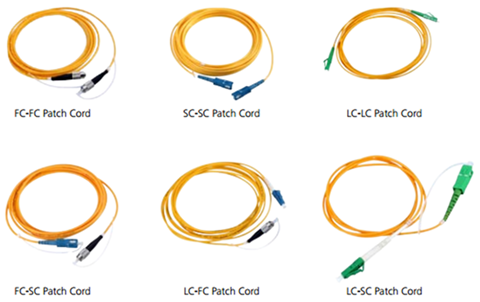
Compared with their copper wires, fiber optic jumpers have smaller diameter, lighter weight, easier for testing and installation. But their advantages are not limited to these points.
- Great Bandwidth
Fiber optic cables can carry very wide bandwidth signals, well into the GHz range. Many individual, lower bandwidth signals can be multiplexed onto the same cable. In commercial systems, fiber optic cable often carries a mixture of signal types, including voice, video and data all on the same fiber.
- Noise Immunity & Electrical Isolation
In industrial applications, one of the most important features of fiber optics is the noise immunity. Even in those conditions which are characteristics of prominent and unavoidable noise, fiber optics are unaffected. As for ground loop noise issues, the use of fiber optic patch cord can just eliminate it. Field signals, generated by devices floating at high potentials, can be coupled to other equipment at much lower potentials without the risk of damage. This is particularly preferable in industrial applications.
- Power Budget
While planning the fiber links, the most critical factor to be considered is the power budget specification of the devices being connected. This value tells you the amount of loss in dB that can be present in the link between the two devices before the units fail to perform properly. This value includes line attenuation as well as connector loss.
It’s necessary to mention that fiber optic patch cord is different from the fiber optic pigtail. The former consists of three parts: fiber optic connector+ fiber optic cable+ fiber optic connector, in contrast, the latter includes only two sectors: fiber optic connector+ fiber optic cable. Or put it in another way, when the cable is terminated with fiber connectors on both ends, it’s fiber optic jumper, and when the fiber connector is attached to only one end of the cable, it’s called a fiber optic pigtail.

Although fiber patch cords have been common for many years, there are still some myths about them.
Some people think that fiber jumper is more expensive than its counterpart copper. Actually, since manufacturing costs become down with each passing day, patch cord is less costly than the equivalent copper installation. Once deployed, the subsequent patch cord maintenance cost is also significantly less what copper requires.
It’s true that when terminating fiber cable, attention and care should be taken to avoid breaking the glass core, and some may think that patch cord is very fragile. But in practical use, fiber jumper has proven to be more robust than copper, able to withstand a higher pulling tension than copper, rated for larger temperature ranges.
Fiber patch cords play an important role in completing the end-to-end connections, ideally to be used in industrial and commercial systems. As professional fiber optic product supplier, Fiberstore offers various kinds of patch cords at affordable prices, including LC fiber patch cable mentioned above, SC patch cord, MTP/MPO cable, single mode and multi mode patch cords. If you want to know more information about patch cables or buy such cables for your networking use, please visit Fiberstore.
Posted by: fernxu123 at
02:28 AM
| No Comments
| Add Comment
Post contains 806 words, total size 6 kb.
May 26, 2016
In this big data age featuring high data transmission speed and great capacity, opticalcomponent transmission technology has experienced a crustal movement with each day passing by. The continuous demands of high-definition images, various voice and massive data transmission services, and many Internet and intelligent terminals application, have driven the bandwidth usage to a soaring point. With the advancements in fiber optics technology to meet the demanding bandwidth speeds, active optical cables (AOCs) have emerged. As copper connectivity faces some limitations such as low bandwidth, AOCs have been preferred to accelerate data connectivity for storage, networking, and high-performance computer (HPC) applications.
You may feel at a loss about what is AOC? Why should focus on this product? Here, let’s start with its definition.
An AOC is a wiring technology which accepts the same electrical inputs as a conventional copper cable, but makes use of optical fiber between the connectors. In order to improve the cable’s distance and speed performance without sacrificing its compatibility with standard electrical interfaces, the AOC uses electrical to optical conversion on the cable ends. More specifically, AOC is basically to convert electrical signal into optical signal at Tx, then transfer signal through anti-electromagnetic fiber optics intermediate, and vice versa at Rx, so that high-speed optical signal can flow smoothly in both ends. Its smart integration of optical and electrical interfaces thanks to the packaging design has expanded its applications from high performance computers to traditional data centers with the support of many protocols. (Active optical cables are reliant on protocol named InfiniBand.). Image below shows the AOC structure.

Key advantages of AOCs include: low weight for high port count architectures; small bend radius for easy installations; and low power consumption enabling a greener environment thereby providing the lowest total cost solution for data centers. At present, AOC is widely used in many fields, such as short-range multi-lane data communication and interconnect applications, to promote the traditional data center to step into optical interconnection.
Being one of the fastest growing technologies in the data center space, AOC has much to offer. It supplies higher bandwidth and a longer reach with a better footprint than current copper cables. When compared to the incumbent copper cables in most cases, active optical cables provide lighter weight, a smaller size, EMI immunity, a lower interconnection loss, and reduced power requirements. It seems that this kind of cable has nothing to "complain aboutâ€, but AOC is such a smart inventor that distinguishes from their predecessors and makes them look obsolete.
In the telecommunication market, a wide range of AOCs have been released for different applications, like 40G QSFP+ to QSFP+ AOCs (QSFP cables). Besides, FOR 40GbE applications, there are also fan-out products with one QSFP+ module (ie. AFBR-79EQPZ) at one end of the AOC and several lesser data rate SFP+ modules (eg. SFP-10G-SR) at the other. These can be used to connect a switch port to multiple server ports.

In addition to 40Gbps, AOCs operating at 100Gbps have also been available in the market for several years. In 100GbE environment, CFP is used for longer distances—typically over 100 meters and up to 40km—while QSFP and CXP is used for shorter distances. And the current cabling application of 100G QSFP28 AOC is one QSFP28 to four SFP28 cables, something similar to that 40G QSFP+ AOC assembly. There seems to be few AOCs that have adopted CFP at the present time.
AOCs provide a direct electrical connection between corresponding cable ends by embedding optics and/or electronics within the connectors. Fiberstore AOCs are provided for HPC, storage and networking applications. Many AOC products are available, including 10G SFP+ AOCs, QSFP cables mentioned above, compatible with Generic, Cisco, Brocade and some other brands. Certainly, AOCs can also be customized to meet your length requirements. For more information, please visit Fiberstore.
Posted by: fernxu123 at
04:24 AM
| No Comments
| Add Comment
Post contains 649 words, total size 5 kb.
May 24, 2016
To meet the growing requirements of collaborative multimedia services and applications, to respond to the fast-changing traffic patterns, and to better accommodate users’ bandwidth demands, 100G connections have been positioned for significant growth in data centers with the introduction of the latest 100G optical modules. The upgrade to 100Gbps is not more than gaining capacity. It’s also about gracefully evolving your network at your own pace to achieve greater efficiency, streamline costs and support new services. Many systems now support four or more 100G ports on each line card, with some systems supporting many hundreds of 100G ports. 100G optical modules, as an integral part of the overall system design, support highly reliable operations, optimized for entire architecture. This article puts its focus on one predominant 100G form factor: QSFP28.
100G QSFP28 transceivers are commonly seen in two types: QSFP28 100GBASE-SR4 (QSFP28 SR4) and QSFP28 100GBASE-LR4 (QSFP28 LR4), designed with four 25Gbps lanes for high port-count 100G data center applications, enabling the implementation of various reaches in the QSFP28 MSA form factor in 100G systems. They allow for greater port density, lower power consumption and significantly lower cost of ownership for 100G connectivity. With these optical transceivers, state-of-the-art 100Gbps performance and new levels of infrastructure consolidation have been made possible.

The QSFP28 100GBASE-SR4 transceiver is a parallel 100Gbps QSFP28 optical module designed with form factor, optical/electrical connection and digital diagnostic interface according to the QSFP28 Multi-Source Agreement (MSA). It offers 4 independent transmit and receive channels, each capable of 25Gbps operation for an aggregated data rate of 100Gbps for 100 meters on 12-fiber MPO/MTP OM4 multi-mode fiber (MMF). Often, an optical fiber ribbon cable with an MTP/MPO connector can be plugged into the QSFP28 module receptacle for high functionality and feature integration. Proper alignment is ensured by the guide pins inside the receptacle. The cable usually cannot be twisted for proper channel to channel alignment.
The QSFP28 SR4 module is a vertically integrated solution that meets IEEE 802.3 standards and MSA requirements with power dissipation well under 3.5W. It supports both 100GBASE-SR4 as well as 4x25G breakout applications, say 100G QSFP28 to QSFP28 DAC and 100G QSFP28 SR4 to 4x25G SFP28 break-out cables, meeting the harshest external operating conditions including temperature, humidity and EMI interference.
- QSFP28 100GBASE-SR4 Working Principle
QSFP28 SR4 transceiver converts parallel electrical input signals into parallel optical signals, by a driven Vertical Cavity Surface Emitting Laser (VCSEL) array. The transmitter module accepts electrical input signals compatible with Common Mode Logic (CML) levels. All input data signals are differential and internally terminated. The receiver module then converts parallel optical input signals via a photo detector array into parallel electrical output signals. The receiver module outputs electrical signals are also voltage compatible with Common Mode Logic (CML) levels. All data signals are differential and support a data rates up to 25Gbps per channel. The following figure shows the functional block diagram of this module.

The QSFP28 100GBASE-LR4 transceiver is also a 100Gbps transceiver module designed for optical communication applications, compliant to 100GBASE-LR4 of the IEEE P802.3ba standard. This module converts 4 input channels of 25Gbps electrical data to 4 channels of LAN WDM optical signals and then multiplexes them into a single channel for 100Gbps optical transmission. Reversely on the receiver side, the module de-multiplexes a 100Gbps optical input into 4 channels of LAN WDM optical signals and then converts them to 4 output channels of electrical data. The high performance cooled LAN WDM EA-DFB transmitters and high sensitivity PIN receivers provide superior performance for 100GbE applications up to 10km links over single-mode fibers (SMFs) and compliant to optical interface with IEEE802.3ba Clause 88 100GBASE-LR4 requirements.
- QSFP28 100GBASE-LR4 Working Principle
The transceiver module receives 4 channels of 25Gbps electrical data, which are processed by a 4-channel Clock and Data Recovery (CDR) IC that reshapes and reduces the jitter of each electrical signal. Subsequently, each of 4 EML laser driver IC's converts one of the 4 channels of electrical signals to an optical signal that is transmitted from one of the 4 cooled EML lasers which are packaged in the Transmitter Optical Sub-Assembly (TOSA). Each laser launches the optical signal in specific wavelength specified in IEEE802.3ba 100GBASE-LR4 requirements. These 4 lane optical signals will be optically multiplexed into a single fiber by a 4-to-1 optical WDM MUX. The optical output power of each channel is maintained constant by an automatic power control (APC) circuit. The transmitter output can be turned off by TX_DIS hardware signal and/or 2-wire serial interface. Here goes the picture of QSFP28 100GBASE-LR4 module functional block diagram.

100G connectivity is now ready for widespread deployment. With so many 100G modules (CFP, CFP2, CFP4 and QSFP2 having been introduced in the market, the number of companies deploying 100GbE networks is sure to see a significant growth. Although the expense of 100G connectivity maybe an issue for some companies, further developments which are under way are expected to reduce the cost.
100G QSFP28 transceivers enable higher speeds, greater scalability, and higher levels of performance and reliability, so as to better meet business demands. To optimize business investment, Fiberstore supplies many 100G QSFP28 modules which experience rigorous qualification and certification testing, sold at affordable prices. Besides QSFP28 transceivers, QSFP28 cable can also be found here. If you want to know more information about QSFP28 optics, you can visit Fiberstore.
Posted by: fernxu123 at
03:09 AM
| No Comments
| Add Comment
Post contains 909 words, total size 8 kb.
22 queries taking 0.0837 seconds, 70 records returned.
Powered by Minx 1.1.6c-pink.

